Data transfer within the PLC
852
Part III FP Instructions
Variable Data type Function
s1 Specifies the bank/slot number in the shared memory of the
intelligent module
s2
ANY16
Starting address for data in the shared memory of the CPU
n INT Specifies the number of words to be written to the shared
memory
d ANY16 Specifies the starting address in the intelligent unit for storing
data written (destination address)
For Relay T/C Register Constant
s1 WX WY WR WL SV EV DT LD FL dec. or hex.
s2 - WY WR WL SV EV DT LD FL -
n WX WY WR WL SV EV DT LD FL dec. or hex.
d WX WY WR WL SV EV DT LD FL dec. or hex.
No. IEC address Set If
R9007 %MX0.900.7 permanently
R9008 %MX0.900.8 for an instant
s1 exceeds the limit of specified range
the data read exceeds the area of d
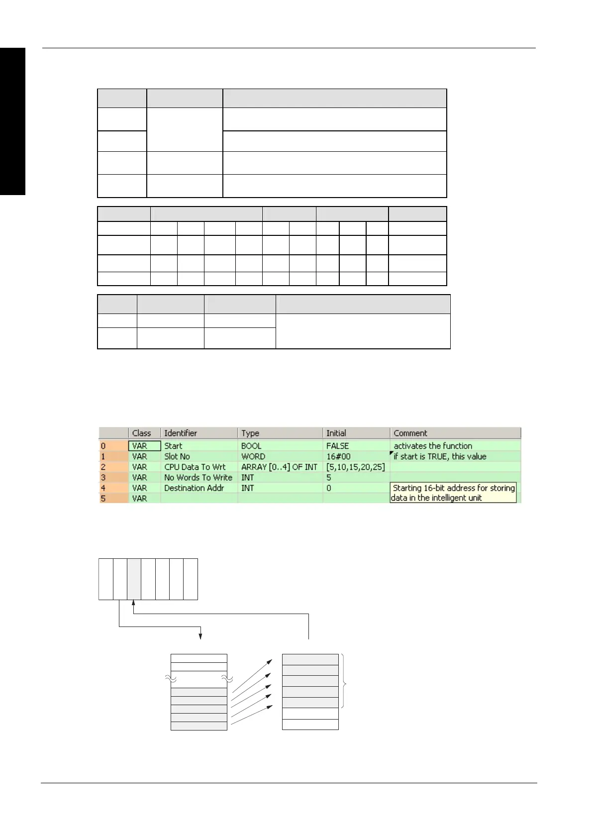
Five words of data defined in CPUDataToWrt are written into the addresses starting from 0 to 4 of
the intelligent unit's shared memory (located in slot 0) when Start turns on.
01234
CPU
0
2
1
3
4
5
6
CPU
rt[0]CPUDataToW
CPUDataToWrt[1]
CPUDataToWrt[2]
CPUDataToWrt[3]
CPUDataToWrt[4]
Power
(Slot No.)
5 words
Intelligent unit
Data types
Operands
Error flags
Example
In this example the function has been programmed in ladder diagram (LD) and structured text
(ST).The same POU header is used for all programming languages.
POU header
All input and output variables used for programming this function have been declared in the POU
header.
Body

 Loading...


