FP-e display instructions
972
Part III FP Instructions
No. IEC Address Set If
R9007 %MX0.900.7 permanently
R9008 %MX0.900.8 temporarily
when the area defined by index modifiers
is greater than the area allowed
the value for s1 or s2 is invalid
You cannot enter the special data register “DT9***” for the lower
display area.
You cannot use this instruction in an interrupt program.
Error flags
Example
In this example the function has been programmed in ladder diagram (LD) and structured text
(ST).The same POU header is used for all programming languages.
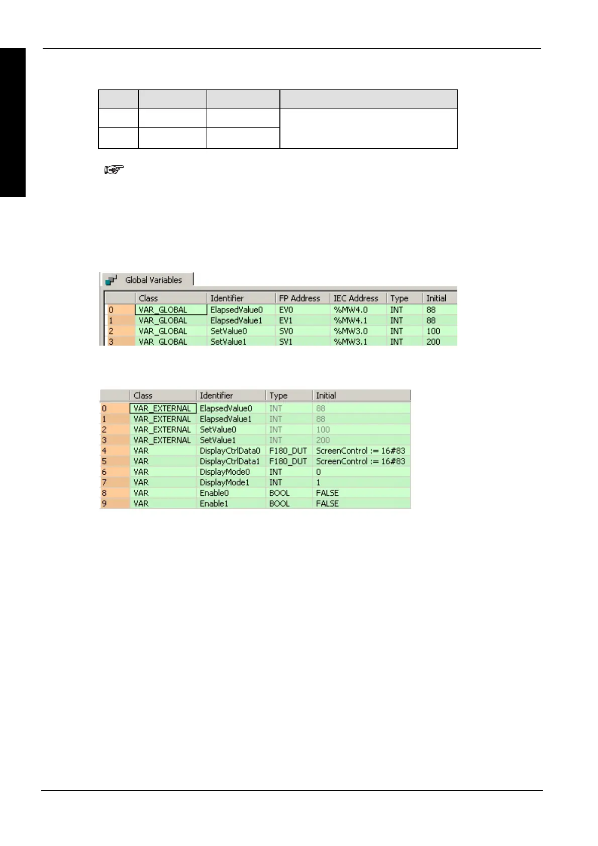
GVL
In the global variable list, you define variables that can be accessed by all POUs in the project.
POU header
All input and output variables used for programming this function have been declared in the POU
header.
Body
When the variable Enable0 is set to TRUE, the function is executed and the FP-e is switched to N
mode, 1st screen. ProcessValue0 and SetValue0 are displayed in the upper and lower sections in
red and orange. When the variable Enable1 is set to TRUE, the function is executed and the FP-e
is switched to N mode, 2nd screen. ProcessValue1 and SetValue1 are displayed in the upper and
lower sections in red and green. The monitor value icon is activated for both LD bodies. Use the
instruction F181_DSP (see page 974) to change the display of the FP-e.

 Loading...


