Figures
xii Quantum DXi6900 G1 User’s Guide
Figure 76 Physical Device Discovery Page. . . . . . . . . . . . . . . . . . . . . 135
Figure 77 DXi6900 G1 Node Integrated Storage Controller. . . . . . . 136
Figure 78 Checking Integrated Storage Controller Status . . . . . . . . 137
Figure 79 Removing and Installing the Integrated Storage Controller
Card . . . . . . . . . . . . . . . . . . . . . . . . . . . . . . . . . . . . . . . . . . . . . . 138
Figure 80 Checking Data-at-Rest Encryption Status . . . . . . . . . . . . . 140
Figure 81 PERC RAID BIOS - Virtual Disk Management . . . . . . . . . . 141
Figure 82 PERC RAID BIOS - Security Key Management . . . . . . . . . . 142
Figure 83 PERC RAID BIOS - Create Security Key . . . . . . . . . . . . . . . 142
Figure 84 PERC RAID BIOS - Key Import . . . . . . . . . . . . . . . . . . . . . . 143
Figure 85 PERC RAID BIOS - Verifying Imported Drives . . . . . . . . . . 143
Figure 86 DXi6900 G1 Node Integrated Storage Controller Battery. 144
Figure 87 Checking Integrated Storage Controller Battery Status . . 146
Figure 88 Removing and Installing the Integrated Storage Controller
Battery . . . . . . . . . . . . . . . . . . . . . . . . . . . . . . . . . . . . . . . . . . . . 147
Figure 89 DXi6900 G1 Node Network Daughter Card . . . . . . . . . . . 148
Figure 90 Checking Network Daughter Card Status. . . . . . . . . . . . . 149
Figure 91 Removing and Installing the Network Daughter Card . . . 150
Figure 92 DXi6900 G1 Node Processor and Heatsink. . . . . . . . . . . . 152
Figure 93 Checking Processor and Heatsink Status . . . . . . . . . . . . . 154
Figure 94 Removing and Installing the Processor Heatsink . . . . . . . 155
Figure 95 Processor Shield Opening and Closing Lever Sequence . . 156
Figure 96 Removing and Installing a Processor . . . . . . . . . . . . . . . . 157
Figure 97 DXi6900 G1 Node Hard Drive Backplane . . . . . . . . . . . . . 160
Figure 98 Removing and Installing the Hard Drive Backplane . . . . . 161
Figure 99 Hard Drive Backplane Cabling Diagram . . . . . . . . . . . . . . 162
Figure 100 DXi6900 G1 Node System Board . . . . . . . . . . . . . . . . . . 164
Figure 101 Removing and Installing the Mini SAS Cable Connector 166
Figure 102 Removing and Installing the System Board . . . . . . . . . . 167
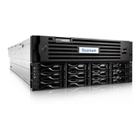
Figure 103 DXi6900 G1 Node . . . . . . . . . . . . . . . . . . . . . . . . . . . . . 173
 Loading...
