Chapter 3: FRU Removal and Replacement Procedures
Replacing the Node Chassis
Quantum DXi6900 G1 User’s Guide 179
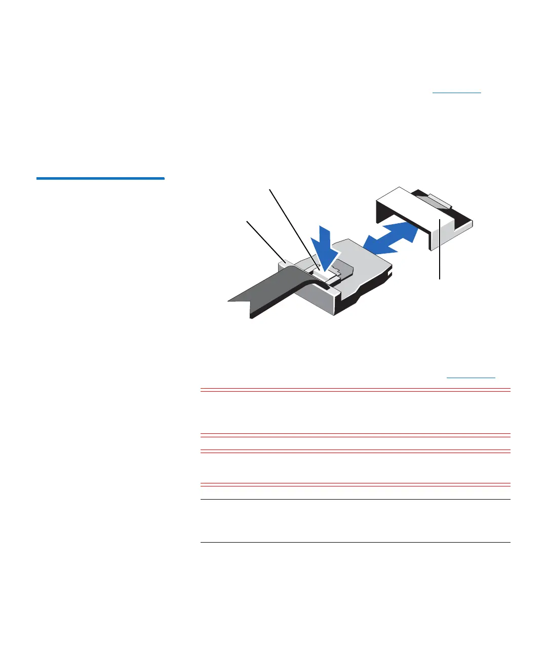
a Push the mini SAS cable connector to slide it further into the
connector (J_SASX8) on the system board (see
Figure 106).
b Press down and hold the metal tab on the mini SAS cable
connector.
c Pull the mini SAS cable out of the connector on the system
board.
Figure 106 Removing and
Installing the Mini SAS Cable
Connector
6 Disconnect all cables from the system board.
7 Grasp the system board holder, lift the blue release pin, and slide
the system board toward the front of the system (see
Figure 107).
Caution: Take care not to damage the system identification
button while removing the system board from the
chassis.
Caution: Do not lift the system board assembly by grasping a
memory module, processor, or other components.
Note: Leave the CPUs and heatsinks, memory modules, and
network daughter card installed in the system board. There
is no need to remove these components.
Metal tab
Connector on the
system board
Mini SAS cable
connector

 Loading...


