Chapter 1: Basic Operations
DXi6900 G1 Node
6 Quantum DXi6900 G1 User’s Guide
Node Rear Panel
Connectors
Figure 5 shows the connectors located on the rear panel of the DXi6900
G1 Node. Tab le describes each item.Ta bl e 3 describes the PCI slot
configuration options.
Note: Refer to the port numbering labels on the back of the Node
chassis to help you determine the correct port connections.
Caution: Do not disconnect any SAS cables from the Node during
normal system operation. Unplugging a SAS cable while
the system is powered on may result in data loss.
10 GbE Cable Types
Depending on the configuration, Quantum DXi6900 G1 systems
support one of the following 10 GbE cable types:
• 10 GbE optical cable lengths of up to 300 meters with OM3
cables and up to 100 meters with OM2 cables - Quantum
recommends using the two 10 meter LC to LC type optical cables
that are shipped with the DXi6900 G1 system. Consult your 10 GbE
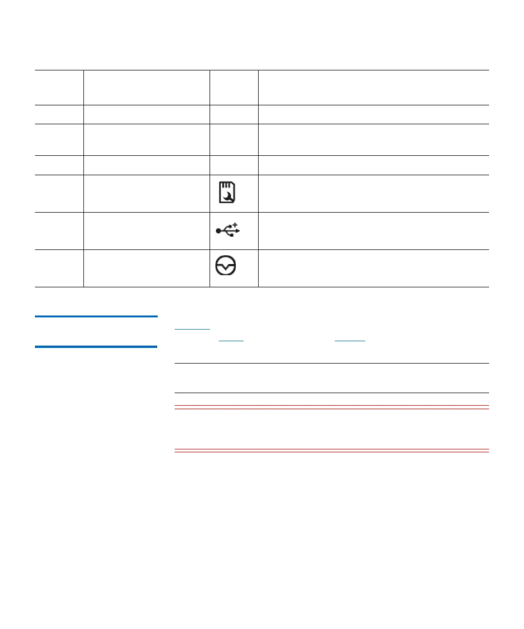
5 LCD panel Lights blue during normal system operation.
6 Information tag A slide-out label panel which displays the system
serial number.
7 Hard drives Sixteen 2.5 inch hot-swappable hard drives.
8 vFlash media card slot Not used.
9 USB 2.0 connectors (2) Allows you to connect USB devices to the system.
The ports are USB 2.0-compliant.
10 NMI button Not used.
Item
Indicator, Button, or
Connector Icon Description

 Loading...


