Chapter 3: FRU Removal and Replacement Procedures
DXi6900 G1 Replacement Cables
230 Quantum DXi6900 G1 User’s Guide
2 Connect all the applicable cables to the control panel (see
Figure 145).
3 Insert the control panel into the slot in the chassis and secure the
module with the screws.
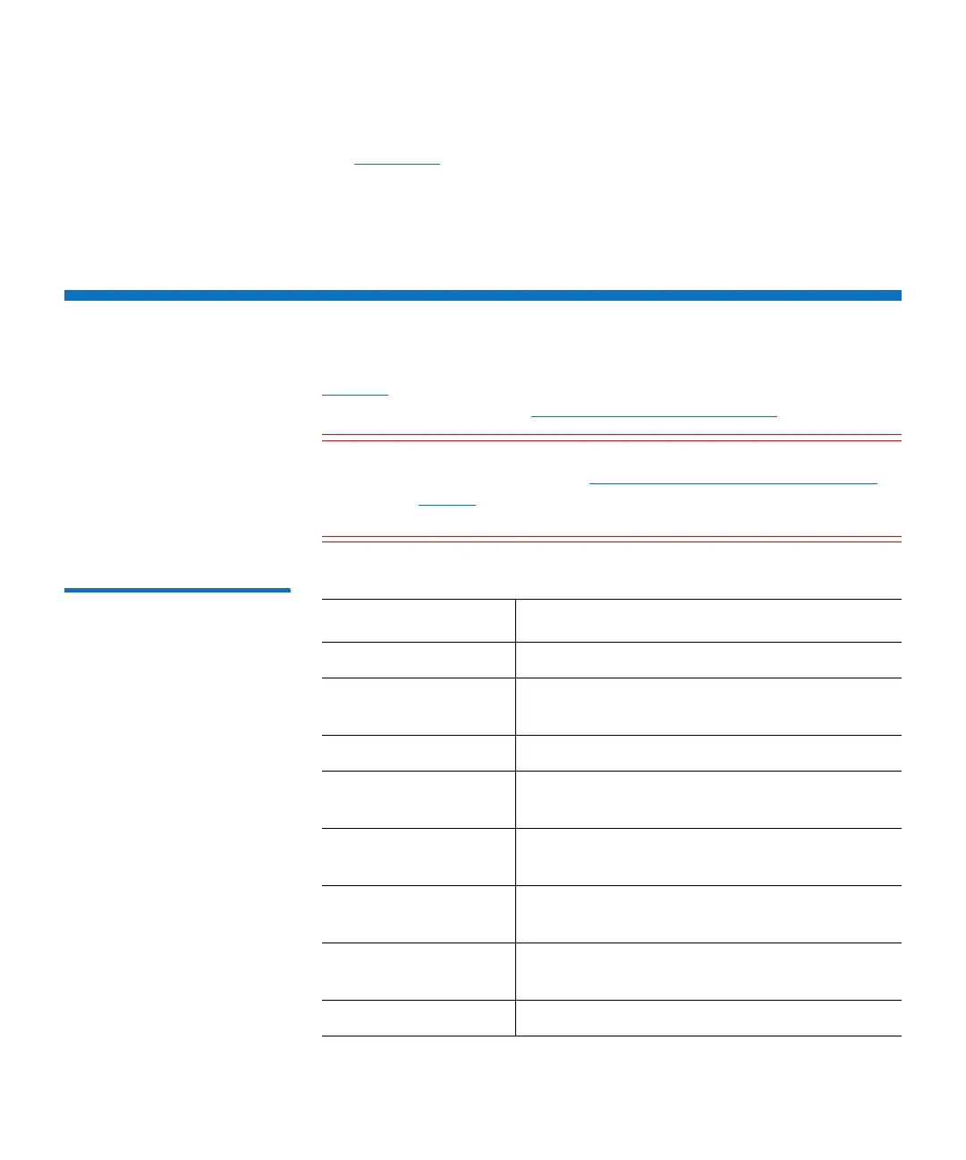
DXi6900 G1 Replacement Cables
Tabl e 16 lists the replacement cables that are available for DXi6900 G1.
For cabling diagrams, see Appendix A, Cabling Diagrams.
Caution: Do not remove any SAS cables until you have shut down
the DXi6900 G1 (see
Turning On and Shutting Down the
System on page 23). If a SAS cable is removed while the
system is running, data may be lost.
Table 16 DXi6900 G1
Replacement Cables
Part Number Description
9-02217-01 Replacement 6 Gb SAS cable, 1 meter
9-03804-01 Replacement Mini-SAS to Mini-SAS HD cable,
2 meter
9-02033-01 Replacement 1 GbE Ethernet cable, 25 feet
9-02036-01 Replacement 10 GbE Ethernet Cable (optical),
6 meter
331-5295 Replacement 10 GbE Ethernet Cable (Twinax),
5 meter
R8H2F Replacement SFP+ module (for use with
optical 10 GbE Ethernet cables)
9-02036-01 Replacement 8 Gb Fibre Channel Cable, 6
meter
0R215 Replacement power cable (5-15 to C13)

 Loading...


