Chapter 3: FRU Removal and Replacement Procedures
Replacing an Array or Expansion Module
Quantum DXi6900 G1 User’s Guide 219
4 Run Factory Detect Hardware from the Service Menu to detect the
new hardware (see
Factory Detect Hardware on page 44).
5 In the remote management console, delete any administrative alerts
and close any service tickets.
Note: In some cases, following replacement of a failed ESM, it is
possible that the drives in the EBOD will be in Optimal state
but the volumes will be in Failed state (see PTR 36565). To
correct this condition while maintaining data integrity, escalate
to Quantum Support (ASPS) and reference NetApp knowledge
base article 2016816.
Replacing an Array or Expansion Module
This section describes how to remove and replace the DXi6900 G1 Array
module (RBOD) or Expansion module (EBOD) chassis and contains the
following sections:
• Obtaining a Replacement Array or Expansion Module Chassis
• Replacing the Array or Expansion Module Chassis
Obtaining a
Replacement Array or
Expansion Module
Chassis
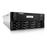
Before beginning the replacement procedure, make sure that you have
the required replacement kit. The appropriate replacement Array
module or Expansion module chassis will be provided by Quantum
Customer Support (see
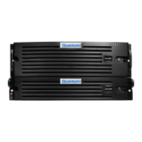
Figure 140).
You will need the following items to perform this procedure:
• Replacement Array module or Expansion module chassis kit
provided by Quantum Customer Support.
• Masking tape and felt tip marker (for temporarily labeling hard
drives)
• # Phillips screwdriver
• ESD grounding wrist strap (included in the replacement kit)
 Loading...
