Chapter 3: FRU Removal and Replacement Procedures
Replacing Node Memory Modules
108 Quantum DXi6900 G1 User’s Guide
7 Check the DSET report entries for DIMM sockets A1–A8 and B1–B8
to locate the failed DIMM.
Note: DIMM sockets A5–A8 and B5–B8 are not populated in
systems with 0–3 Expansion Modules (RBODs) and will
show as Not Occupied. DIMM sockets A9–A12 and B9–B12
always shows as Not Occupied.
Removing a Failed Memory Module from the Node
To remove the failed memory module from the DXi6900 G1 Node:
WARNING: The memory modules are hot to the touch for some time
after the system has been powered down. Allow time for
the memory modules to cool before handling them.
1 Shut down the system (see Turning On and Shutting Down the
System on page 23).
2 Remove the Node cover (see Opening and Closing the Node on
page 78).
3 Locate the failed memory module.
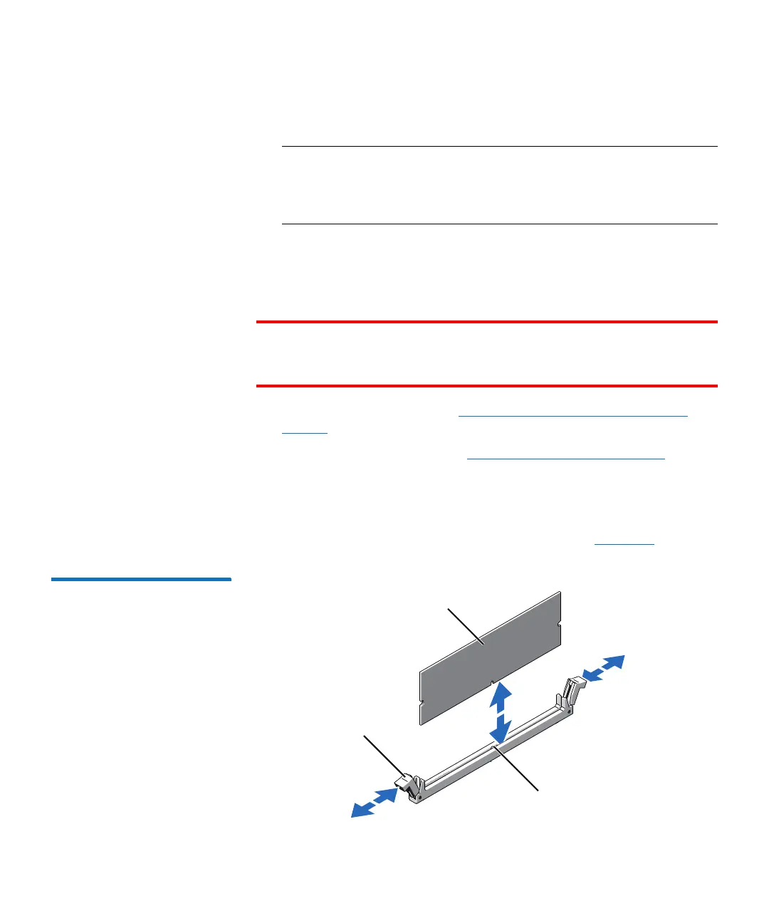
4 Press down and out on the ejectors on each end of the socket until
the memory module pops out of the socket (see
Figure 59).
Figure 59 Removing and
Installing a Memory Module
Memory module
Ejector latch
Socket alignment key

 Loading...


