Chapter 3: FRU Removal and Replacement Procedures
Replacing the Node System Board
164 Quantum DXi6900 G1 User’s Guide
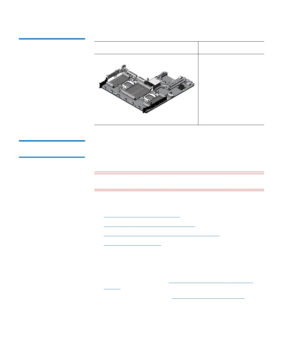
Figure 100 DXi6900 G1 Node
System Board
Replacing the System
Board
This section describes how to remove and replace the system board in
the DXi6900 G1 Node. The system board hosts numerous components,
including the processors, integrated storage controller, network
daughter card, expansion card risers, and cooling fan assembly.
Caution: Use appropriate ESD precautions, including the use of a
grounding strap, when performing this procedure.
Removing and replacing the hard drive backplane in the Node includes
the following steps:
• Removing a Failed System Board
• Installing a Replacement System Board
• Updating the Service Tag and Setting the OEM ID
• Verifying iDRAC Settings
Removing a Failed System Board
To remove the system board from the DXi6900 G1 Node:
1 Shut down the system (see Turning On and Shutting Down the
System on page 23).
2 Remove the Node cover (see Opening and Closing the Node on
page 78).
Illustration Description
Replacement system
board
PN JP31P (TPM)
PN VRCY5 (non-TPM)