Chapter 3: FRU Removal and Replacement Procedures
Replacing Array or Expansion Module Power Supplies
Quantum DXi6900 G1 User’s Guide 199
Figure 122 DXi6900 G1 Array
and Expansion Module Power
Supplies
Use the indicator LEDs on the power supply to identify the failed power
supply (see
Figure 123).
• Standby power (solid green) - Main DC power is off and 5V
standby power is on.
• DC enabled (solid green) - DC power rails are within specified
limits.
• Service action allowed (solid blue) - Safe to remove power supply
from slot.
• Service action required (solid amber) - Power supply has failed
and requires attention.
•AC enabled (solid green) - Power is being applied to the power
supply and the power switch is on.
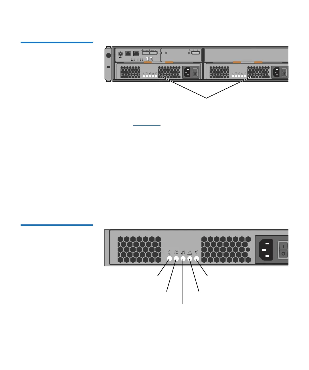
Figure 123 Array and
Expansion Module Power
Supply LEDs
Port 1 Port 2
ID/Diag
Lnk Lnk
Power supplies
Standby power
Service action allowed
DC enabled Service action required
AC enabled

 Loading...


