Chapter 1: Basic Operations
DXi6900 G1 Node
Quantum DXi6900 G1 User’s Guide 5
Table 1 DXi6900 G1 Node -
Front Panel LED Indicators,
Buttons, and Connectors
Item
Indicator, Button, or
Connector
Icon Description
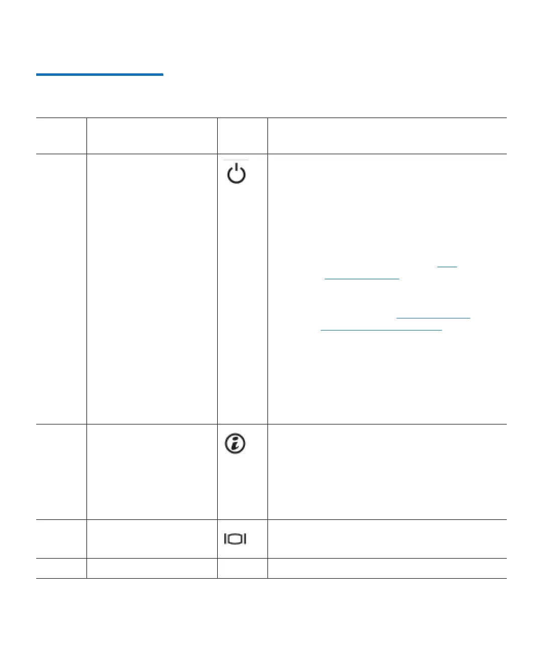
1 Power-on indicator,
power button
The power-on indicator lights when the system
power is on. The power button controls the
power supply output to the system.
Warning: Turning off the power removes the
main power but keeps standby power
supplied to the Node. Because of this,
you must unplug the Node before
servicing unless you are replacing a
hot-swappable part (see
Hot-
Swappable Parts on page 76).
Caution: Turning off the power without properly
shutting down the system may result in
loss of data (see
Turning On and
Shutting Down the System on
page 23).
Note: To shut down the Node in the event of an
emergency, press and hold the power
button for 4 seconds. Warning: This may
result in data loss and may cause a delay
on next startup due to a blockpool verify
operation.
2 System identification
button
Press to toggle the system ID on and off.
The identification buttons on the front and back
panels can be used to locate a particular system
within a rack. When one of these buttons is
pressed, the LCD panel on the front and the
system status indicator on the back flashes until
one of the buttons is pressed again.
3 Video connector Allows you to connect a VGA display to the
system.
4 LCD menu buttons Not used.

 Loading...


