Chapter 3: FRU Removal and Replacement Procedures
Replacing the Node System Board
166 Quantum DXi6900 G1 User’s Guide
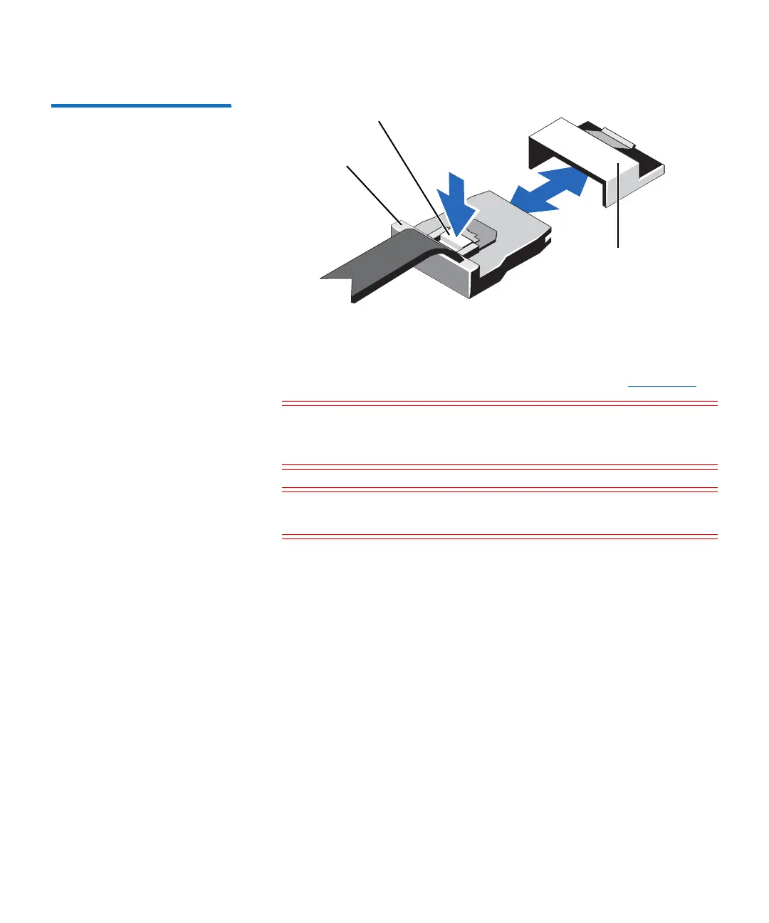
Figure 101 Removing and
Installing the Mini SAS Cable
Connector
6 Disconnect all cables from the system board.
7 Grasp the system board holder, lift the blue release pin, and slide
the system board toward the front of the system (see
Figure 102).
Caution: Take care not to damage the system identification
button while removing the system board from the
chassis.
Caution: Do not lift the system board assembly by grasping a
memory module, processor, or other components.
Metal tab
Connector on the
system board
Mini SAS cable
connector

 Loading...


