RL78/G15 CHAPTER 6 TIMER ARRAY UNIT
R01UH0959EJ0110 Rev.1.10 Page 241 of 765
Mar 7, 2023
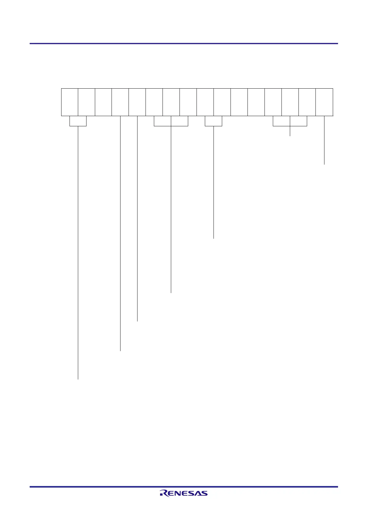
Figure 6-50. Example of Set Contents of Registers During Operation as Frequency Divider (1/2)
(a) Timer mode register 0n (TMR0n)
15 14 13 12 11 10 9 8 7 6 5 4 3 2 1 0
TMR0n
CKS0n
1
CKS0n
0
n
S
Note 1
STS0n
2
STS0n
1
STS0n
0
n
CIS0n
MD0n3
MD0n
MD0n1
n0
1/0 0 0 1 0 0 0 0 1/0 1/0 0 0 0 0 0 1/0
Operation mode of channel n
000B: Interval timer
Setting of operation when
counting is started
0: Neither generates INTTM0n
nor inverts timer output when
counting is started.
1: Generates INTTM0n and
inverts timer output when
counting is started.
Selection of TI0n pin input edge
00B: Detects falling edge.
01B: Detects rising edge.
10B: Detects both edges.
11B: Setting prohibited
Start trigger selection
000B: Selects only software start.
Setting of SPLIT0n bit (channel 3)
0: 16-bit timer mode
Count clock selection
1: Selects the TI0n pin input valid edge.
Operation clock (f
MCK
) selection
00B: Selects CK00 as operation clock of channel n.
10B: Selects CK01 as operation clock of channel n.
Note 1. Channel 3 only
Remark n: Channel number (n = 0, 3)
 Loading...


