15 February 2006 PUNCH UNIT (B531/B812)
1-63
Installation
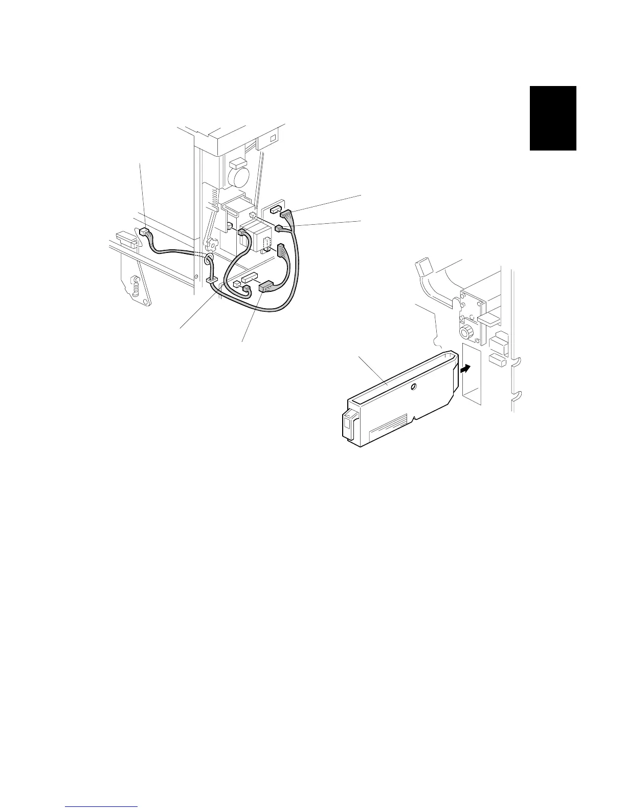
13. Connect the PCB harness connector [A] to CN129 of the finisher PCB and to
CN600 of the punch unit PCB.
14. Connect the HP Sensor 2 harness connector [B] to CN130 of the finisher PCB
and to HP Sensor 2.
15. Connect the single end of the hopper full sensor connector cable [C] to the
hopper full sensor on the arm (# x 1, clamp x 1), then connect the other two
connectors to HP Sensor 1 [D] and CN620 [E] of the punch PCB.
NOTE: No special DIP switch settings are required for this punch unit. The
punch unit sends an identification signal to the machine, so it knows
what type of punch unit has been installed.
16. Slide the hopper [F] into the finisher.
17. Re-attach the inner cover and rear cover.
18. Close the front door and re-connect the finisher to the machine.
B531I007.WMF
B531I008.WMF
[A]
[B]
[C]
[D]
[E]
[F]