OnAir Digital Mixing Consoles
6-84 Conguration
Document generated: 10.10.14
SW V6.0
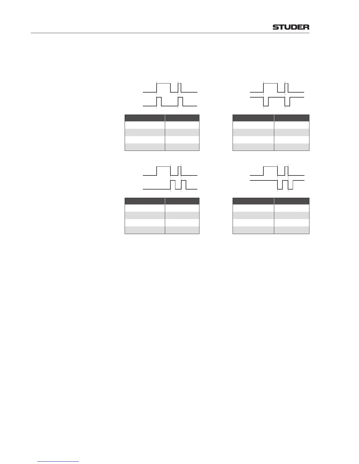
Example 4, Pulse Output Mode
To get a pulse at the output pin, the ‘Triggered Edge’ attribute must be set
to either ‘rising’ or ‘falling’, the ‘Time’ attribute (> 0 ms) defines the pulse
duration.
Level
Output
Pin
Level
Output
Pin
Pin Attributes Setting Pin Attributes Setting
Activate
On
Activate
On
Time
> 0 ms
Time
> 0 ms
Polarity
positive
Polarity
negative
Triggered Edge
rising
Triggered Edge
rising
Level
Output
Pin
Level
Output
Pin
Pin Attributes Setting Pin Attributes Setting
Activate
On
Activate
On
Time
> 0 ms
Time
> 0 ms
Polarity
positive
Polarity
negative
Triggered Edge
falling
Triggered Edge
falling
Notes: • TransparentOutFunction
Active if the value of the specified parameter is different from zero. This
function is normally used for factory testing only.
However, by entering the address of a parameter (i.e., the device ID
number), a particular function may be monitored by a GP output. In this
way it is possible to check, e.g., whether any channel is set to PFL.
Only 64-bit device ID numbers in hex format are accepted as argument
1 – i.e., ‘0x’ followed by 16 digits, such as 0x1122334455667788.
This function is intended for experts only, since localizing a device ID
number requires the ‘Tree Viewer’ application and its handling.
• LinkOutputFunction
This function can be used to link a GP output to another GPIO function.
The linked output may then be set to answer to the same input conditions,
but with different logic – such as a pulse signal, whereas the original GP
output is a continuous signal.
• ForwardInput
This function can be used to mirror a GP input status of a remote stage
box on a GP output of the console I/O system, if the remote stage box is
connected to the I/O system via a MADI link.

 Loading...


