OnAir Digital Mixing Consoles
6-94 Conguration
Document generated: 10.10.14
SW V6.0
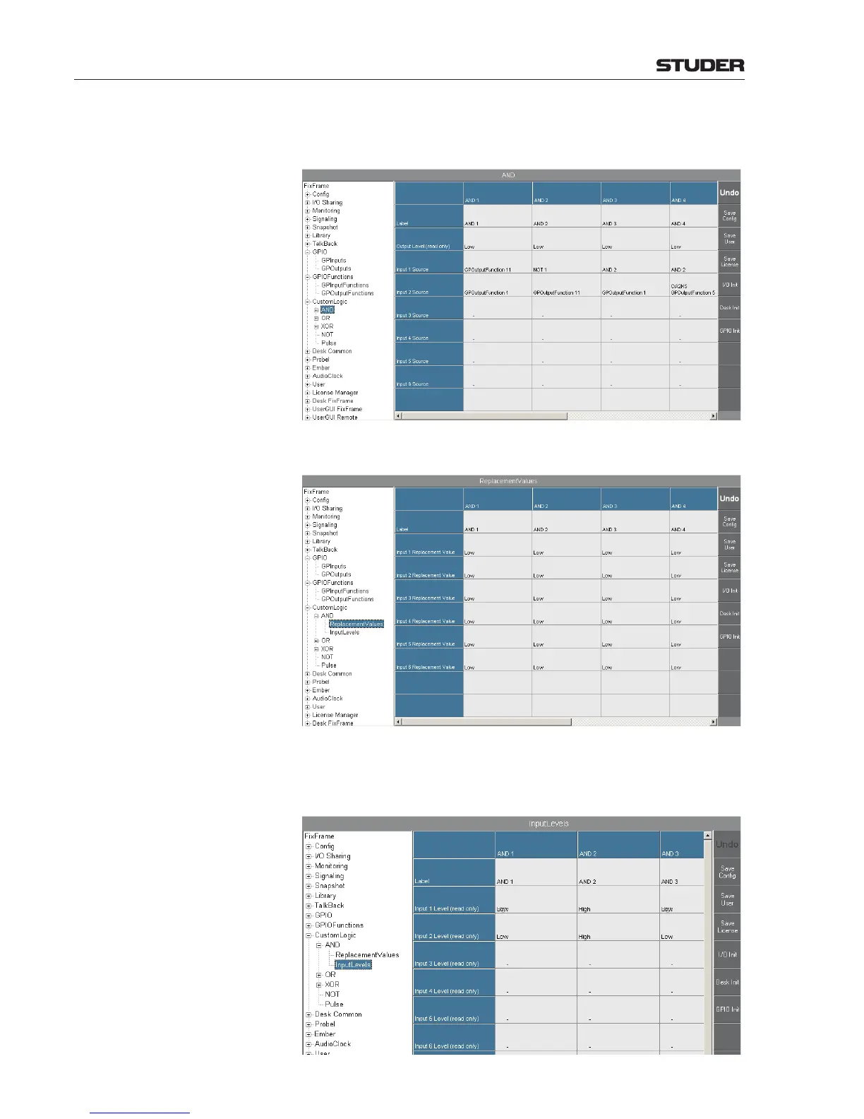
Step 5 In the AND section, perform the settings as shown below; the gate and gate
input designators correspond to the ones in the logic diagram above.
Step 6 Set all ReplacementValues for the AND gates 1-4 to Low.
Step 7 In the AND – InputLevels page (this is a read-only page) you will see the
input no. 1 levels of AND gates 1 and 3 alternating since they are connected
to the generator’s output.
 Loading...


