OnAir Digital Mixing Consoles
Conguration 6-99
Document generated: 10.10.14
SW V6.0
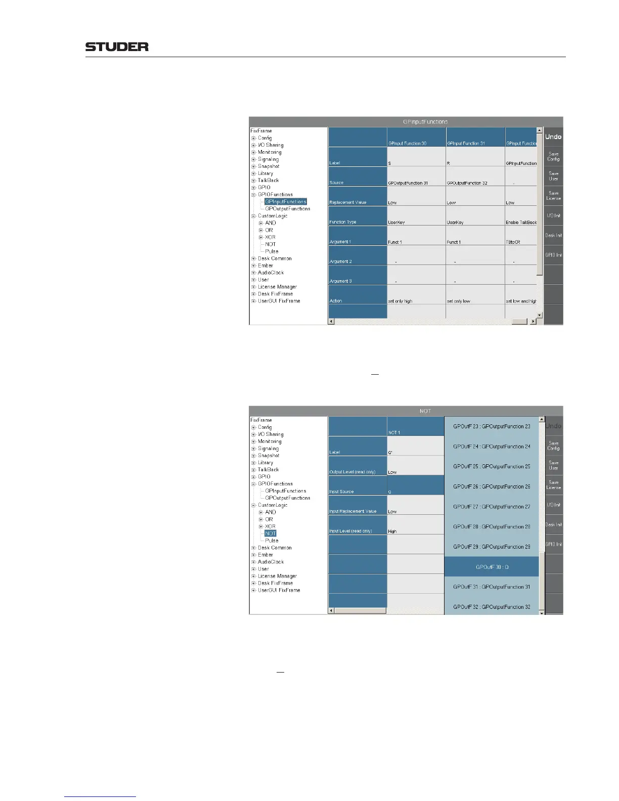
parameters to rising Edge. For clearness you may want to label them as S
and R.
Step 2 Configure GPOutputFunction 30 as UserKey and its argument as Funct 1.
If desired, you may label it as Q. (refer to the first screenshot of this example
on the previous page).
Step 3 If you also need an inverted Q output, configure the NOT1 gate as shown
below, and label it Q’:
Step 4 Remember to set the Activate parameter of all used GPIO and Custom Logic
functions to On.
When switching now the CDR 1 and CDR 2 channels on/off, you will see the
Q and Q
signals change as intended: CDR 1 (S) on will cause Q – the input
signal of the inverter – to go high and Q’ low, as shown above. This status
will remain stable when switching CDR 1 off and on again. It will change only
when channel CDR 2 (R) is switched on (Q goes low and Q’ high) and again
remain stable, no matter what you do with the CDR 2 channel afterwards, as
shown in the next screenshot.
 Loading...


