OnAir Digital Mixing Consoles
6-98 Conguration
Document generated: 10.10.14
SW V6.0
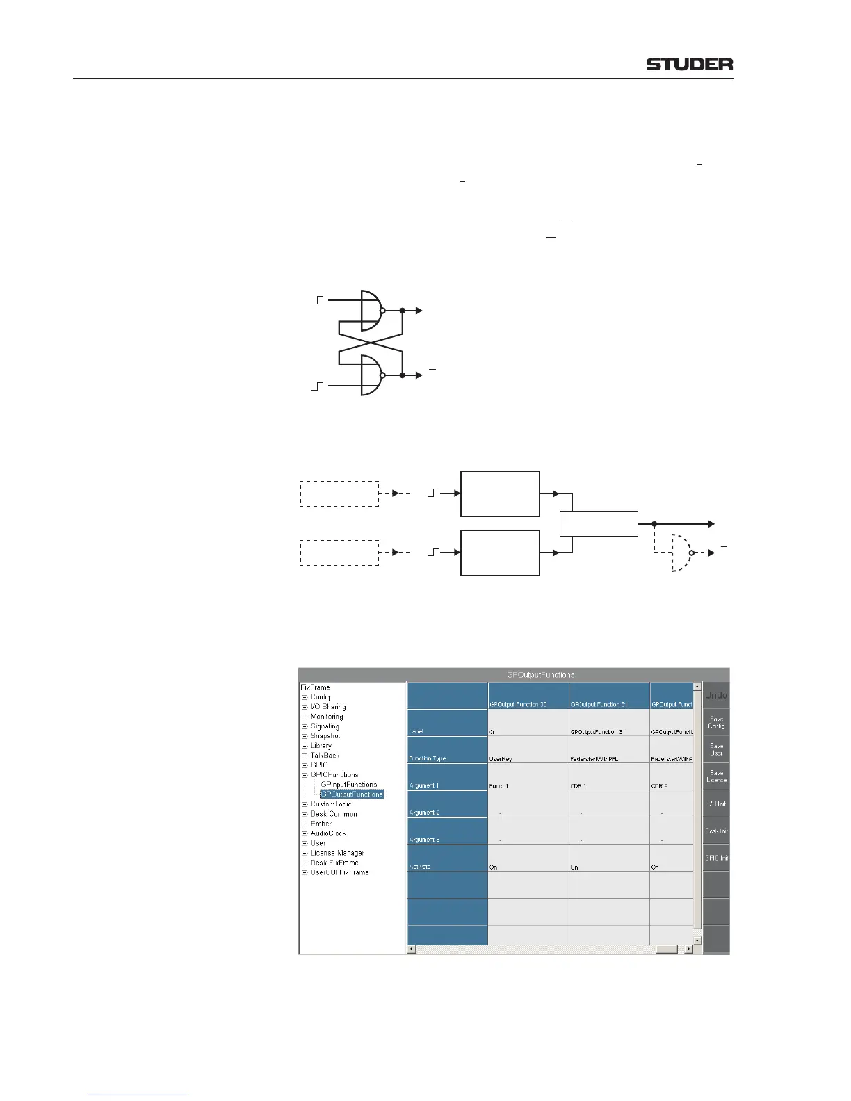
Example 3 - Emulating an RS Flip-Flop
An RS flip-flop is a logic element that has two stable logic output states (on
and off) controlled by two different inputs; one of them (S) is used to set the
output (Q), the second (R) to reset it (hence the name). It can be composed, for
example, from a pair of cross-coupled logic NOR gates, but is also available
in integrated form (e.g. as TTL or CMOS ICs). Usually the output signal is
available both non-inverted (Q) and inverted (Q
). The diagram below shows
an RS flip-flop circuit. The outputs (Q and Q) both change their state on the
rising edge of the R and S inputs.
Q
Q
S
R
Since feedback connections are not allowed within Custom Logic, a configu-
ration as the one suggested below is recommended.
GPInputFunction 30
UserKey, Funct 1
Set Only High
Rising Edge
GPInputFunction 31
UserKey, Funct 1
Set Only Low
Rising Edge
GPOutputFunction 30
UserKey, Funct 1
GPOutputFunction 31
(Fader Start CDR 1)
GPInputFunction 32
(Fader Start CDR 2)
R
S
Q
Q
NOT
1
In our example, we have two GP output functions, such as the fader start of
two CD players (GP output functions 31 and 32). We want to use them as S
and R signals for our flip-flop emulation.
Step 1 Configure two GP input functions (nos. 30 and 31 in our example) as User-
Key. Set their Source to GPOutputFunction 31 and GPOutputFunction
32. Set their no. 1 arguments to Funct 1. Define Action as set only high
for one, and as set only low for the second one. Set both TriggeredEdge
 Loading...


