OnAir 3000 Digital Mixing Console
Operating Elements 4-11
Document generated: 10.10.14
SW V6.0
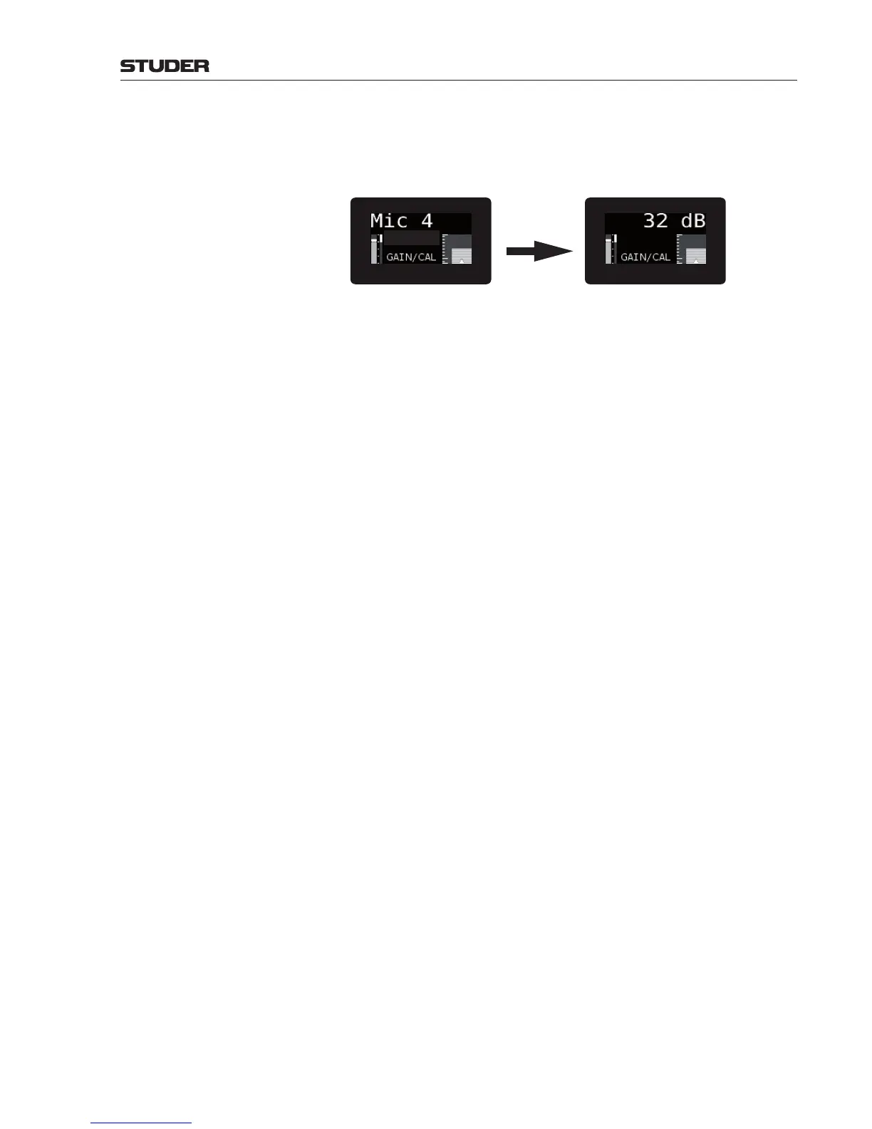
Channel Label / (Value) The 8-digit channel label area normally indicates the (local or remote) channel
label if a logical input is assigned to the channel strip. As long as its rotary
knob is touched, the display shows the current parameter value, depending
on the selected function.
Rotary Touch
Second Label The 2nd label area is used exclusively for indication of the I/O sharing
producer system name. It is blanked as long as the rotary is touched, except
during input channel routing.
Rotary Parameter The rotary parameter area indicates the parameter name if a rotary function
is assigned this channel.
Rotary Graph The rotary graph area shows a graphical representation of the value of the
assigned rotary function.
Level Meter A bar graph level meter is provided in each channel’s OLED display, either
indicatingtheinputlevel,ortheN–XorAUXsendlevelofthechannel(con-
figurable). The value indicated on the meter is depending on the console’s
headroom setting (default value: 0 dB indication for –9 dB
FS
).
N–X or AUX Send Level Indication: InthismodethelevelmeterindicatestheN–XortheAUXsendlevelofthe
channel.
Overload Indication, Analog Inputs: As soon as one sample at an analog input reaches full scale modulation, the
overload indicator is on for approx. 300 ms (the idea is that the probability
of an A/D converter reaching full scale without clipping is close to zero. Any
full scale levels within the path are considered to be overloads).
Overload Indication, Digital Inputs: Full scale modulation at a digital input is not considered to be an overload – it
is simply the output level of a source.
Overload Indication, REC/PGM Outputs:
If one sample of an output signal reaches full scale, the corresponding over-
load indication is on for approx. 300 ms.
Auto Take-Over Indication: On the non-motorized fader modules, the physical value and the internal,
processed value of the fader may be different. This can be the case after
routing, snapshot, or CAB changes – or simply because a fader value has
been changed with the GUI rotary encoder. If the values are different, auto
take-over mode is enabled. The channel display indicates by FDR UP or
FDR DOWN in which direction the fader knob has to be moved. As soon
as the fader knob has been moved a bit, the display changes to a numerical
value, such as -15 UP or 27 DOWN. When the fader position matches the
internal value, TAKEOVER flashes three times; the whole process is quite
self-explanatory.
If optional motor faders are installed, their physical positions automatically
follow the internal processed values; no auto take-over indication is required
then.
Gain Reduction Meter The meter is able to indicate either Compressor/Limiter gain redunction,
DeEsser gain reduction or the channels voice mix control gain (if VoiceMix-
option is available).
Softbuttons on the MainScreen allow selection of the desired indication.