12.9 L: Protection Functions
890 YASKAWA SIEPC71061705H GA700 Series Technical Manual
Note:
1. To connect a dynamic braking option (braking resistor or braking resistor unit) to the drive, set this parameter to 0 or 3. Parameter
values 1, 2, 4, and 5 will enable Stall Prevention function during deceleration, and the dynamic braking option will not function.
2. The setting range changes when the A1-02 [Control Method Selection] value changes:
• When A1-02 = 5 [OLV/PM], the setting range is 0 to 2.
• When A1-02 = 6, 7, 8 [AOLV/PM, CLV/PM, EZOLV], the setting range is 0, 1.
Stall Prevention during deceleration controls the deceleration as specified by the DC bus voltage and does not let
high inertia or fast deceleration cause ov [Overvoltage] faults.
0 : Disable
The drive decelerates as specified by the deceleration time. If the deceleration time is too short, the drive can
detect an ov fault.
Note:
If an ov fault occurs, connect a dynamic braking option to the drive. If an ov fault occurs after you connect a dynamic braking option and
A1-02 = 0 or 2 [Control Method Selection = V/f or CLV] and L3-04 = 0, set L3-04 = 3.
1 : General Purpose
The drive decelerates as specified by the deceleration time. When the DC bus voltage is more than the Stall
Prevention level, the drive stops deceleration until the DC bus voltage is less than the Stall Prevention Level. The
drive then starts to decelerate at the set deceleration time. Frequent use of Stall Prevention will help prevent ov
faults when the deceleration time is shorter than the drive can usually accept.
Note:
The Decel Stall Prevention function will increase the deceleration time to stop and the deceleration time will be longer than the setting.
This function is not applicable for conveyor applications because the precision of the stop position is very important. As an alternative,
use a dynamic braking option in these applications.
The input voltage setting of E1-01 [Input AC Supply Voltage] sets the DC bus voltage level for Stall Prevention.
Table 12.73 Stall Prevention Level during Deceleration
Drive Input Voltage Stall Prevention Level during Deceleration
200 V Class 377 V
400 V Class 754 V
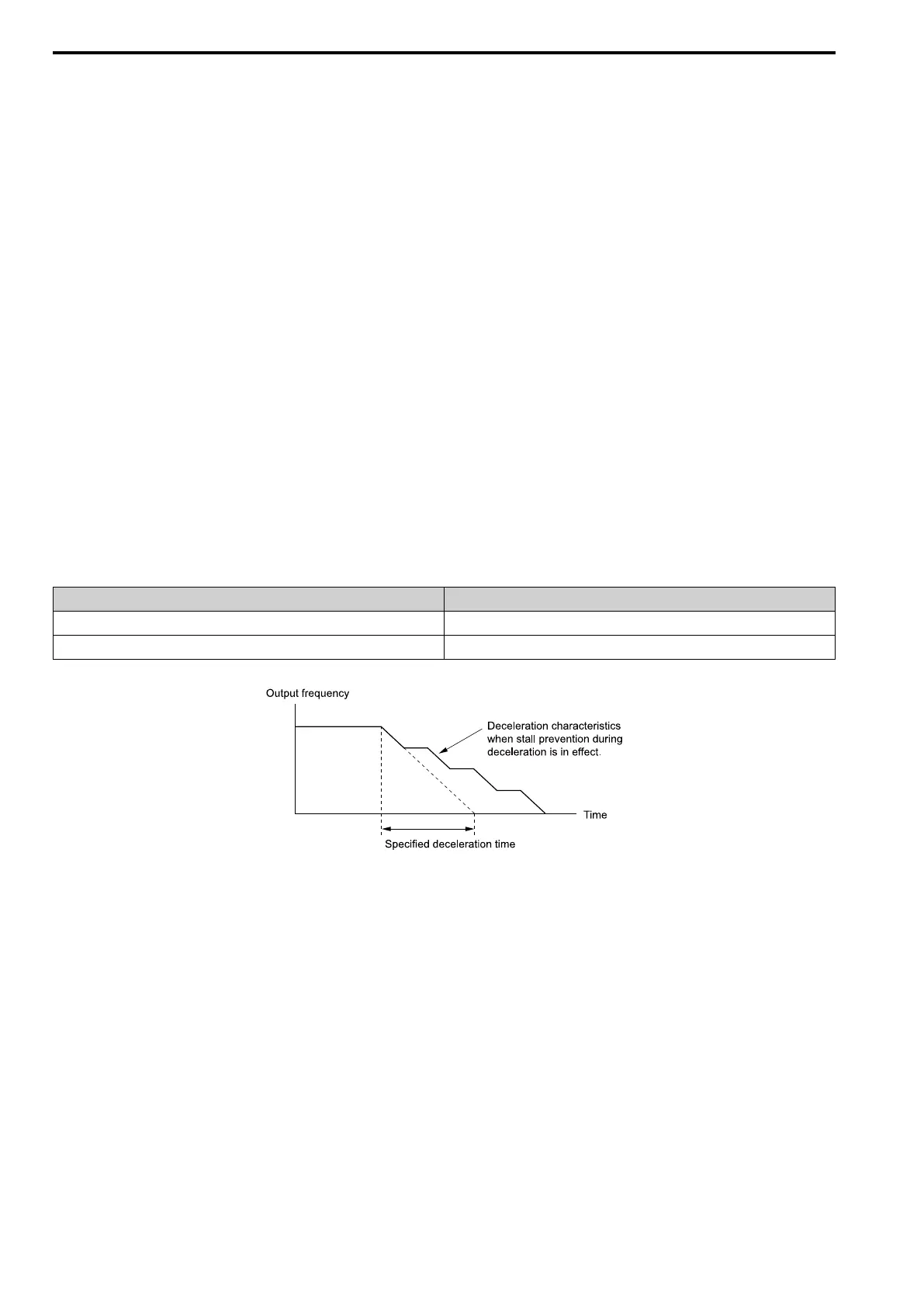
Figure 12.137 shows the Stall Prevention during deceleration function.
Figure 12.137 Stall Prevention Operation during Deceleration
2 : Intelligent (Ignore Accel Ramp)
The drive adjusts the deceleration rate to keep the DC bus voltage at the L3-17 [DC Bus Regulation Level] level.
This makes the shortest possible deceleration time and will not let the motor stall. The drive ignores the selected
deceleration time and the possible deceleration time cannot be less than 1/10 of the set deceleration time.
This function uses these parameters to adjust the deceleration rate:
• L3-20 [DC Bus Voltage Adjustment Gain]
• L3-21 [OVSuppression Accel/Decel P Gain]
• L3-24 [Motor Accel Time @ Rated Torque]
• L3-25 [Load Inertia Ratio]
Note:
The deceleration time is not constant. For applications where the precision of the stop position is very important, use a dynamic braking
option and set L3-04 = 0. If an ov occurs, set L3-04 = 3.
3 : General Purpose w/ DB resistor
A braking resistor is necessary for this setting. The braking resistor and the drive work together for the Stall
Prevention during deceleration function.

 Loading...


