Chapter 8: Configuration and Remote System Upgrades in Cyclone IV Devices 8–41
Configuration
May 2013 Altera Corporation Cyclone IV Device Handbook,
Volume 1
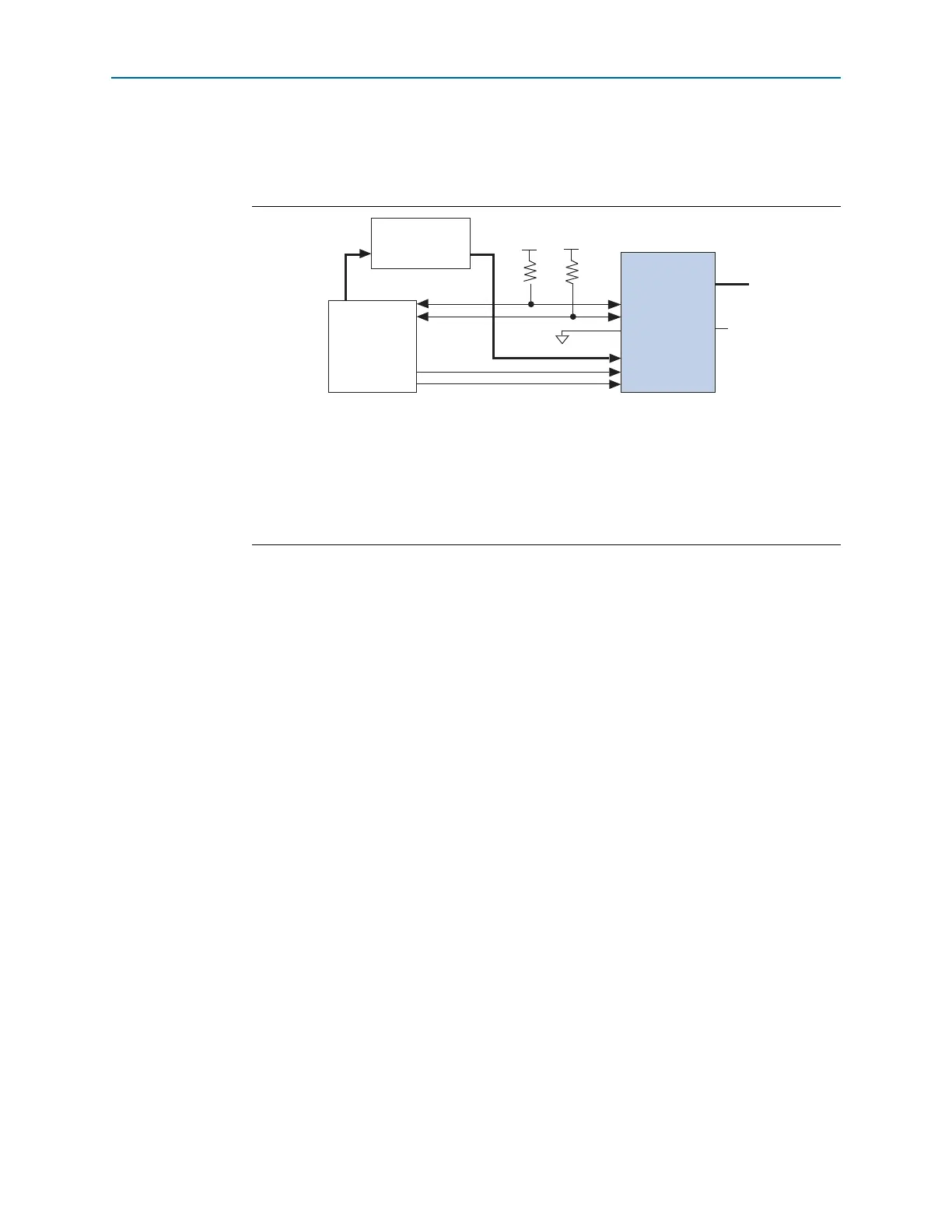
the device, must be stored in the external host device. Figure 8–19 shows the
configuration interface connections between the Cyclone IV devices and an external
device for single-device configuration.
After
nSTATUS
is released, the device is ready to receive configuration data and the
configuration stage begins. When
nSTATUS
is pulled high, the external host device
places the configuration data one byte at a time on the
DATA[7..0]
pins.
Cyclone IV devices receive configuration data on the
DATA[7..0]
pins and the clock is
received on the
DCLK
pin. Data is latched into the device on the rising edge of
DCLK
.
Data is continuously clocked into the target device until
CONF_DONE
goes high. The
CONF_DONE
pin goes high one byte early in FPP configuration mode. The last byte is
required for serial configuration (AS and PS) modes.
1 Two
DCLK
falling edges are required after
CONF_DONE
goes high to begin initialization
of the device.
Supplying a clock on
CLKUSR
does not affect the configuration process. After the
CONF_DONE
pin goes high,
CLKUSR
is enabled after the time specified as t
CD2CU
. After
this time period elapses, Cyclone IV devices require 3,192 clock cycles to initialize
properly and enter user mode. For more information about the supported
CLKUSR
f
MAX
value for Cyclone IV devices, refer to Table 8–13 on page 8–44.
The
INIT_DONE
pin is released and pulled high when initialization is complete. The
external host device must be able to detect this low-to-high transition, which signals
the device has entered user mode. When initialization is complete, the device enters
user mode. In user mode, the user I/O pins no longer have weak pull-up resistors and
function as assigned in your design.
Figure 8–19. Single-Device FPP Configuration Using an External Host
Notes to Figure 8–19:
(1) Connect the pull-up resistor to a supply that provides an acceptable input signal for the device. V
CC
must be high
enough to meet the V
IH
specification of the I/O on the device and the external host.
(2) The
nCEO
pin is left unconnected or used as a user I/O pin when it does not feed the
nCE
pin of another device.
(3) The
MSEL
pin settings vary for different configuration voltage standards and POR time. To connect the
MSEL
pins,
refer to Table 8–4 on page 8–8 and Table 8–5 on page 8–9. Connect the
MSEL
pins directly to V
CCA
or GND.
(4) All I/O inputs must maintain a maximum AC voltage of 4.1 V.
DATA[7..0]
and
DCLK
must fit the maximum overshoot
outlined in Equation 8–1 on page 8–5.
External Host
(MAX II Device or
Microprocessor)
Memory
ADDR
Cyclone IV Device
nSTATUS
CONF_DONE
10 k
nCE
nCEO
DATA[7..0]
GND
V
CCIO
(1)
V
CCIO
(1)
10 k
MSEL[3..0]
N.C. (2)
DATA[7..0]
(4)
nCONFIG
DCLK
(4)
(3)