Chapter 5: Clock Networks and PLLs in Cyclone IV Devices 5–15
Clock Networks
October 2012 Altera Corporation Cyclone IV Device Handbook,
Volume 1
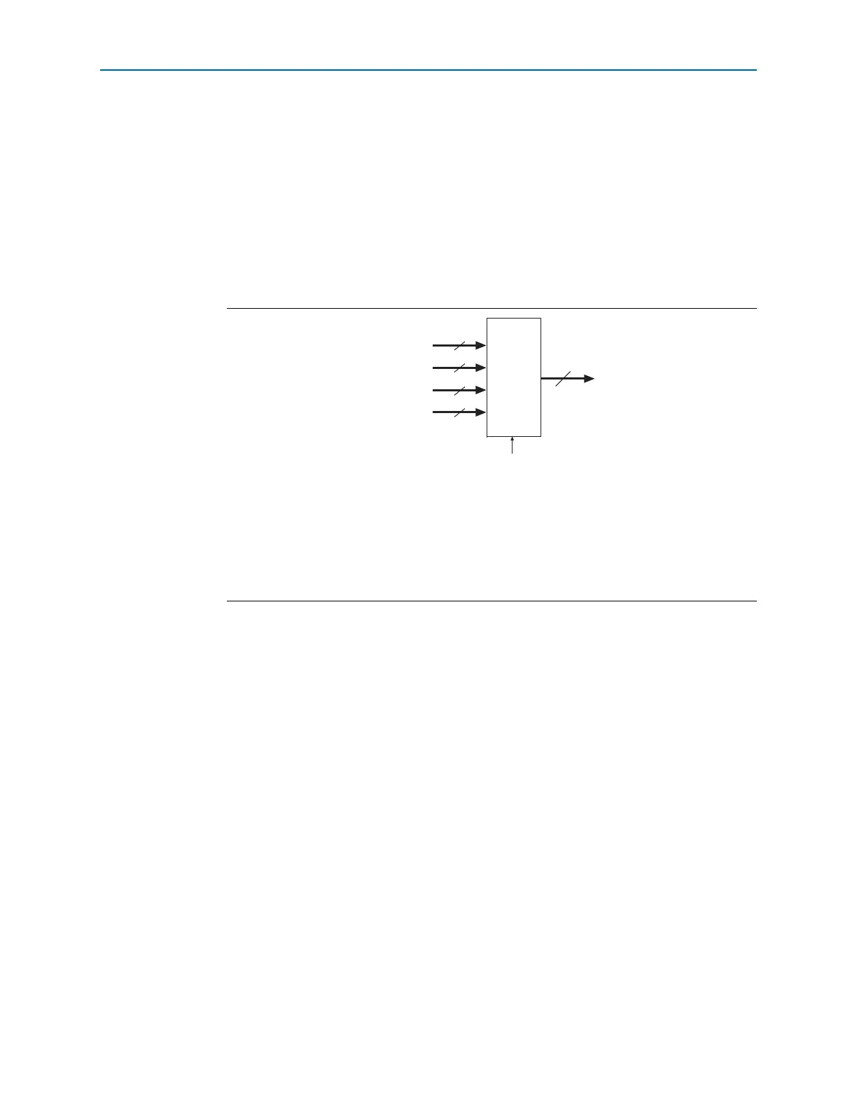
From the clock sources listed above, only two clock input pins, two out of four PLL
clock outputs (two clock outputs from either adjacent PLLs), one
DPCLK
pin, and one
source from internal logic can drive into any given clock control block, as shown in
Figure 5–1 on page 5–11.
Out of these six inputs to any clock control block, the two clock input pins and two
PLL outputs are dynamically selected to feed a GCLK. The clock control block
supports static selection of the signal from internal logic.
Figure 5–5 shows a simplified version of the clock control blocks on each side of the
Cyclone IV GX device periphery.
The inputs to the five clock control blocks on each side of the Cyclone IV E device
must be chosen from among the following clock sources:
■ Three or four clock input pins, depending on the specific device
■ Five PLL counter outputs
■ Two
DPCLK
pins and two
CDPCLK
pins from both the left and right sides and four
DPCLK
pins from both the top and bottom
■ Five signals from internal logic
From the clock sources listed above, only two clock input pins, two PLL clock outputs,
one
DPCLK
or
CDPCLK
pin, and one source from internal logic can drive into any given
clock control block, as shown in Figure 5–1 on page 5–11.
Out of these six inputs to any clock control block, the two clock input pins and two
PLL outputs are dynamically selected to feed a GCLK. The clock control block
supports static selection of the signal from internal logic.
Figure 5–5. Clock Control Blocks on Each Side of Cyclone IV GX Device
Notes to Figure 5–5:
(1) The EP4CGX15 device has two
DPCLK
pins; the EP4CGX22 and EP4CGX30 devices have four
DPCLK
pins; the
EP4CGX50, EP4CGX75, EP4CGX110, and EP4CGX150 devices have six
DPCLK
pins.
(2) Each clock control block in the EP4CGX15, EP4CGX22, and EP4CGX30 devices can drive five GCLK networks. Each
clock control block in the EP4CGX50, EP4CGX75, EP4CGX110, and EP4CGX150 devices can drive six GCLK
networks.
5 or 6 (2)
GCLK
Clock Input Pins
4
DPCLK (1)
Internal Logic
Clock
Control
Block
10
PLL Outputs
5
2, 4, or 6
Five or six clock control
blocks on each side
of the device