Altera Corporation 2–25
July 2005 Stratix Device Handbook, Volume 2
TriMatrix Embedded Memory Blocks in Stratix & Stratix GX Devices
Power-up Conditions & Memory Initialization
Upon power-up, TriMatrix memory is in an idle state. The M512 and M4K
block outputs always power-up to zero, regardless of whether the output
registers are used or bypassed. Even if a memory initialization file is used
to pre-load the contents of the RAM block, the outputs still power-up
cleared. For example, if address 0 is pre-initialized to FF, the M512 and
M4K blocks power-up with the output at 00.
M-RAM blocks do not support memory initialization files; therefore, they
cannot be pre-loaded with data upon power-up. M-RAM blocks
combinatorial outputs and memory controls always power-up to an
unknown state. If M-RAM block outputs are registered, the registers
power-up cleared. The undefined output appears one clock cycle later.
The output remains undefined until a read operation is performed on an
address that has been written to.
Read-During-
Write Operation
at the Same
Address
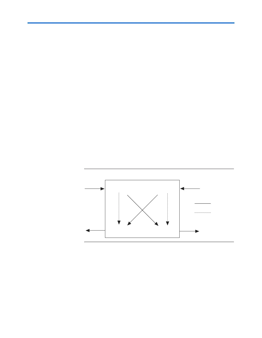
The following two sections describe the functionality of the various RAM
configurations when reading from an address during a write operation at
that same address. There are two types of read-during-write operations:
same-port and mixed-port. Figure 2–14 illustrates the difference in data
flow between same-port and mixed-port read-during-write.
Figure 2–14. Read-During-Write Data Flow
Same-Port Read-During-Write Mode
For read-during-write operation of a single-port RAM or the same port of
a true dual-port RAM, the new data is available on the rising edge of the
same clock cycle it was written on. This behavior is valid on all memory-
block sizes. See Figure 2–15 for a sample functional waveform.
Port A
data in
Port B
data in
Port B
data out
Port A
data out
Same-port
data flow
Mixed-port
data flow