5–12 Altera Corporation
Stratix Device Handbook, Volume 2 July 2005
Principles of SERDES Operation
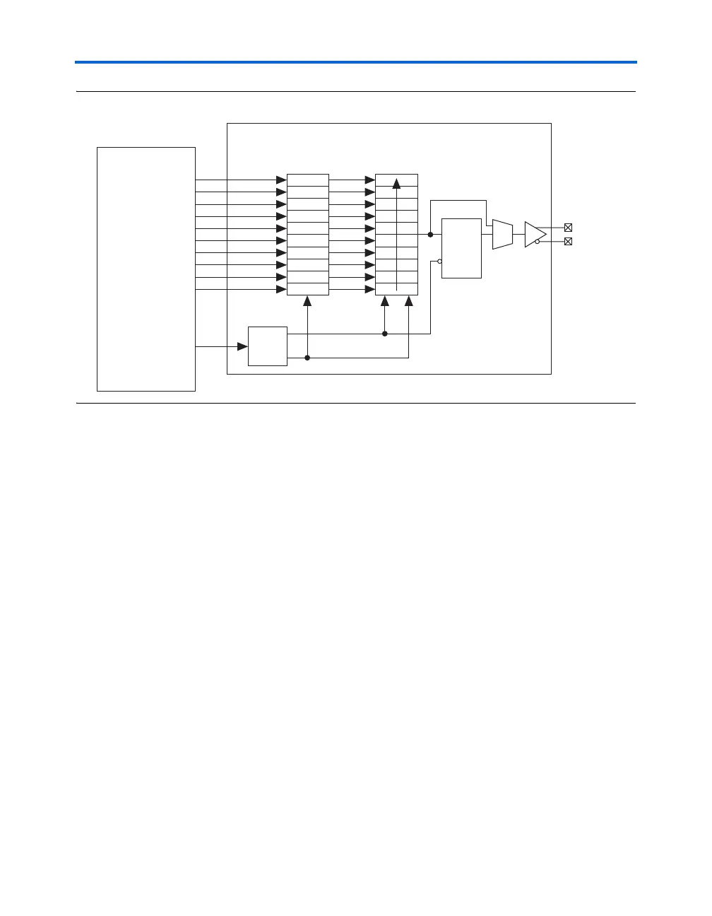
Figure 5–7. Stratix Programmable Transmitter Clock
SDR Transmitter Clock Output
You can route the high-frequency clock internally generated by the PLL
out as a transmitter clock output on any of the differential channels. The
high-frequency clock output allows Stratix devices to support
applications that require a 1-to-1 relationship between the clock and data.
The path of the high-speed clock is shown in Figure 5–8. A programmable
inverter allows you to drive the signal out on either the negative edge of
the clock or 180º out of phase with the streaming data.
PD9
PD8
PD7
PD6
PD5
PD4
PD3
PD2
PD1
PD0
PD9
PD8
PD7
PD6
PD5
PD4
PD3
PD2
PD1
PD0
Stratix
Logic Array
Transmitter Circuit
Parallel
Register
Serial
Register
Fast
PLL
TXOUT+
TXOUT−
×
W
TXLOADEN