Altera Corporation 5–21
July 2005 Stratix Device Handbook, Volume 2
High-Speed Differential I/O Interfaces in Stratix Devices
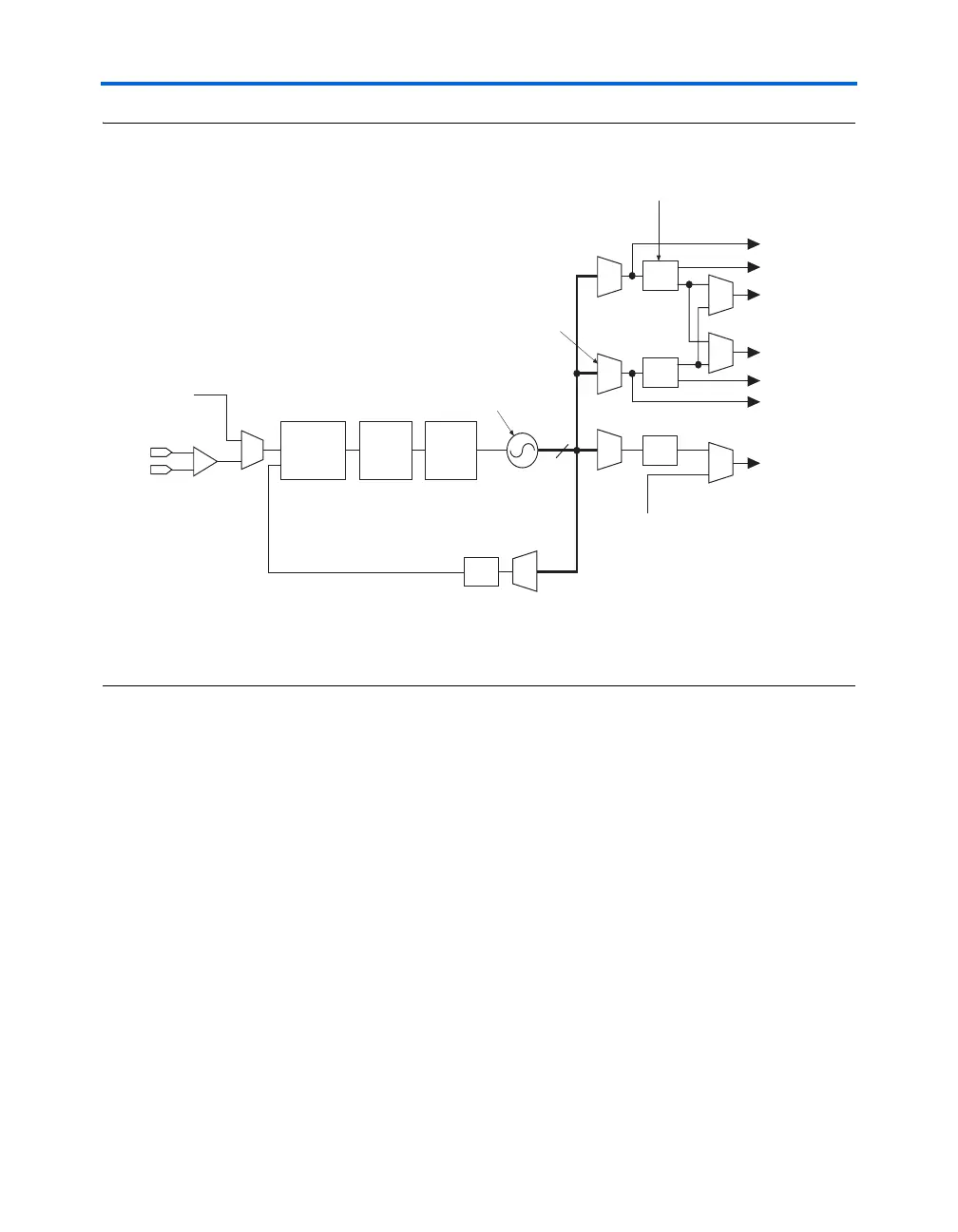
Figure 5–14. Fast PLL Block Diagram
Notes to Figure 5–14:
(1) In high-speed differential I/O mode, the high-speed PLL clock feeds the SERDES. Stratix devices only support one
rate of data transfer per fast PLL in high-speed differential I/O mode.
(2) Control signal for high-speed differential I/O SERDES.
You can multiply the input clock by a factor of 1 to 16. The multiplied
clock is used for high-speed serialization or deserialization operations.
Fast PLL specifications are shown in the Stratix Device Family Data Sheet
section of the Stratix Device Handbook, Volume 1. The voltage controlled
oscillators (VCOs) are designed to operate within the frequency range of
300 to 840 MHz, to provide data rates of up to 840 Mbps.
High-Speed Phase Adjust
There are eight phases of the multiplied clock at the PLL output, each
delayed by 45° from the previous clock and synchronized with the
original clock. The three multiplexers (shown in Figure 5–14) select one of
the delayed, multiplied clocks. The PLL output drives the three counters
k, v, and l. You can program the three individual post scale counters (k, v,
and l) independently for division ratio or phase. The selected PLL output
is used for the serialization or deserialization process in SERDES.
Charge
Pump
VCO
÷
l
8
Clock Input
Phase
Frequency
Detector
÷
v
÷
k
÷
m
Loop
Filter
VCO Phase Selection
Selectable at each PLL
Output Port
Post-Scale
Counters
Global or
regional clock
Regional clock
Regional clock
DIFFIOCLK2 (1
DIFFIOCLK1 (1
TXLOADEN (2)
RXLOADEN (2)
Global or
regional clock
rxclkin