1–34 Altera Corporation
Stratix Device Handbook, Volume 2 July 2005
Fast PLLs
Clock Multiplication & Division
Stratix and Stratix GX device fast PLLs provide clock synthesis for PLL
output ports using m/(post scaler) scaling factors. The input clock is
multiplied by the m feedback factor. Each output port has a unique post
scale counter to divide down the high-frequency VCO. There is one
multiply counter, m, per fast PLL with a range of 1 to 32. There are three
post-scale counters (g0, l0, and l1) for the regional and global clock output
ports. All post-scale counters range from 1 to 32. If the design uses a
high-speed serial interface, you can set the output counter to 1 to allow
the high-speed VCO frequency to drive the SERDES.
External Clock Outputs
Each fast PLL supports differential or single-ended outputs for source-
synchronous transmitters or for general-purpose external clocks. There
are no dedicated external clock output pins. The fast PLL global or
regional outputs can drive any I/O pin as an external clock output pin.
The I/O standards supported by any particular bank determines what
standards are possible for an external clock output driven by the fast PLL
in that bank. See the Selectable I/O Standards in Stratix & Stratix GX Devices
chapter in the Stratix Device Handbook, Volume 2 or the Stratix GX Device
Handbook, Volume 2 for output standard support.
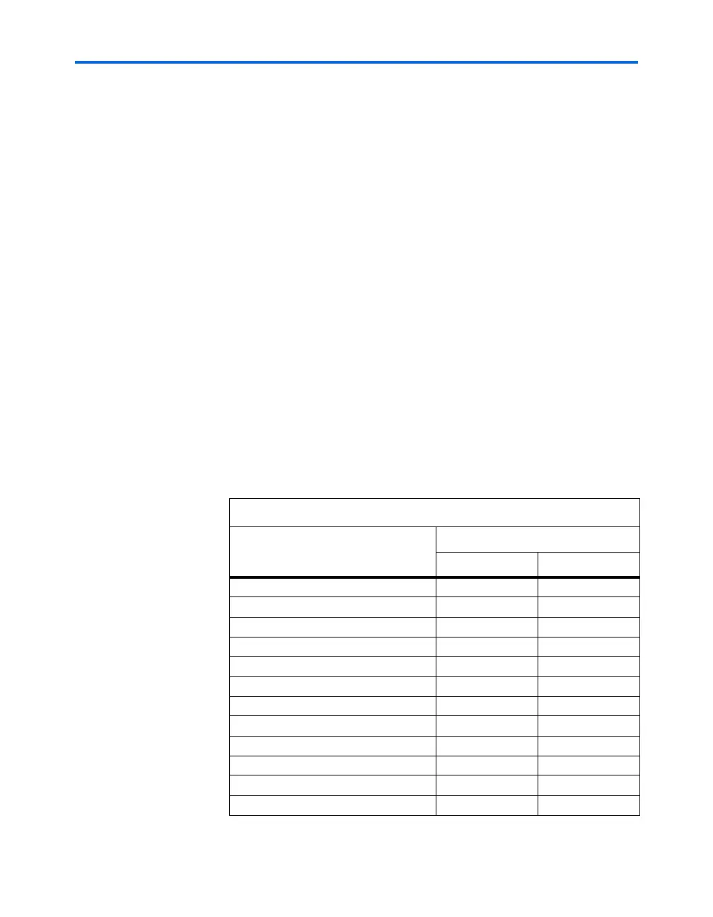
Table 1–12 shows the I/O standards supported by fast PLL input pins.
Table 1–12. Fast PLL Port I/O Standards (Part 1 of 2)
I/O Standard
Input
INCLK PLLENABLE
LVTTL vv
LVCMOS vv
2.5 V v
1.8 V v
1.5 V v
3.3-V PCI
3.3-V PCI-X 1.0
LVPECL v
PCML v
LVDS v
HyperTransport technology v
Differential HSTL v