Altera Corporation 5–31
July 2005 Stratix Device Handbook, Volume 2
High-Speed Differential I/O Interfaces in Stratix Devices
Figure 5–23. Bit Orientation in the Quartus II Software
Differential I/O Bit Position
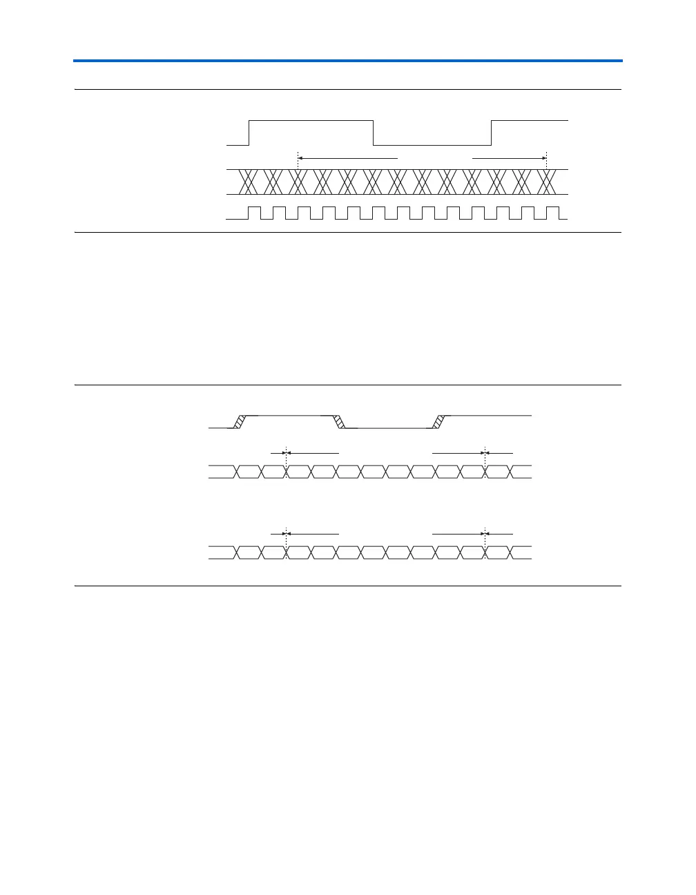
Data synchronization is necessary for successful data transmission at
high frequencies. Figure 5–24 shows the data bit orientation for a receiver
channel operating in
×8 mode. Similar positioning exists for the most
significant bits (MSBs) and least significant bits (LSBs) after
deserialization, as listed in Table 5–5.
Figure 5–24. Bit Order for One Channel of Differential Data
n-1 n-0 9 8 7 6 5 4 3 2 1 0
10 LVDS Bits
MSB LSB
inclock/outclock
data in
high-frequency clock
inclock/outclock
Data in/
Data out
D7 D6 D5 D4 D3 D2 D1 D0
Current CyclePrevious Cycle Next Cycle
Data in/
Data out
1001 0110
Current CyclePrevious Cycle Next Cycle
Example: Sending the Data 10010110
MSB LSB
MSB LSB