5–28 Altera Corporation
Stratix Device Handbook, Volume 2 July 2005
Receiver Data Realignment
TXLOADEN signal is generated by the v counter, and when the v counter
is used for realignment, the TXLOADEN signal is generated by the k
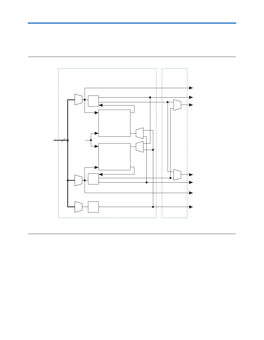
counter, as shown in Figure 5–20.
Figure 5–20. Realignment Circuit TXLOADEN Signal Control Note (1)
Note to Figure 5–20:
(1) This figure does not show additional realignment circuitry.
Realignment Implementation
The realignment signal (SYNC) is used for data realignment and
reframing. An external pin (RX_DATA_ALIGN) or an internal signal
controls the rx_data_align node end. When the rx_data_align
node end is asserted high for at least two low-frequency clock cycles, the
RXLOADEN signal is delayed by one high-frequency clock period and the
parallel bits shift by one bit. Figure 5–21 shows the timing relationship
between the high-frequency clock, the RXLOADEN signal, and the parallel
data.
8
÷
v
÷
k
×1 CLK2 to logic array
×1 CLK1 to logic array
CLK1 LVDS
Circuitry
CLK2 LVDS
Circuitry
GCLK/LCLK
TXLOADEN
RXLOADEN
÷
l
PLL Output
Clock
Distribution
Circuitry
Counter Circuitry
Sync S1
Realignment CLK
Sync S2
Realignment CLK
SYNC
Data
Realignment
Circuit
Data
Realignment
Circuit