Altera Corporation 14–23
January 2005 Stratix Device Handbook, Volume 2
Designing with 1.5-V Devices
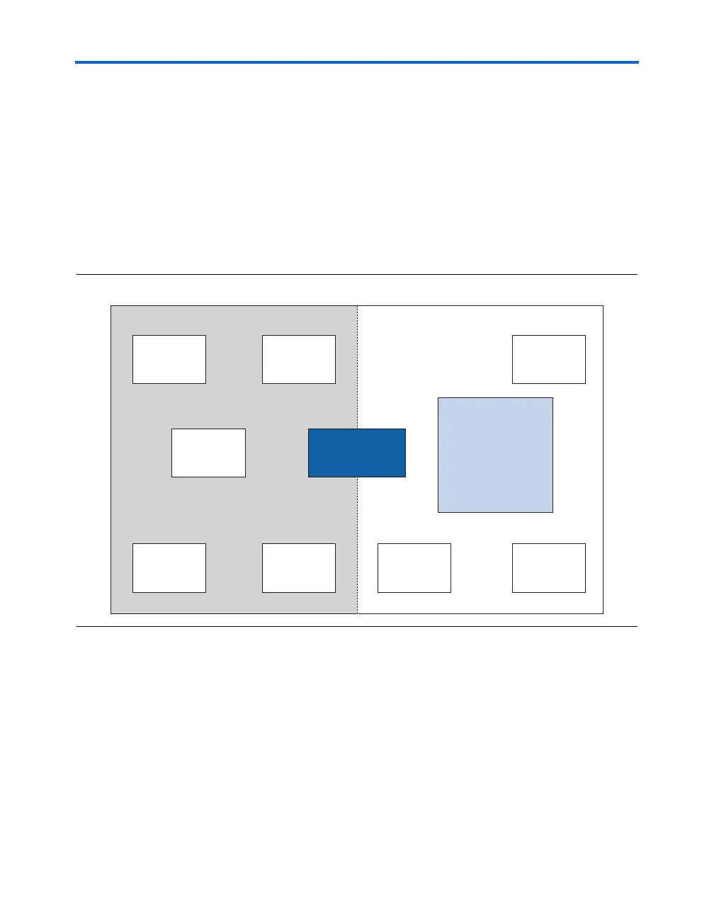
Split-Plane Method
The split-plane design method reduces the number of planes required by
placing two power supply planes in one plane (see Figure 14–20). For
example, the layout for this method can be structured as follows:
■ One 2.5-V plane, covering the entire board
■ One plane split between 5.0-V and 1.5-V
This technique assumes that the majority of devices are 2.5-V. To support
MultiVolt I/O, Altera devices must have access to 1.5-V and 2.5-V planes.
Figure 14–20. Split Board Layout for 2.5-V Systems With 5.0-V & 1.5-V Devices
Conclusion
With the proliferation of multiple voltage levels in systems, it is
important to design a voltage system that can support a low-power
device like Cyclone devices. Designers must consider key elements of the
PCB, such as power supplies, regulators, power consumption, and board
layout when successfully designing a system that incorporates the low-
voltage Cyclone family of devices.
2.5-V
Device
2.5-V
Device
2.5-V
Device
5.0-V
Device
5.0-V
Device
1.5-V
Device
1.5-V
Device
2.5-V
Device
Altera
Cyclone
FPGA
(1.5 V)
1.5 V
PCB
5.0 V
Regulator