Altera Corporation 5–9
July 2005 Stratix Device Handbook, Volume 2
High-Speed Differential I/O Interfaces in Stratix Devices
Stratix Differential I/O Transmitter Operation
You can configure any of the Stratix differential output channels as a
transmitter channel. The differential transmitter is used to serialize
outbound parallel data.
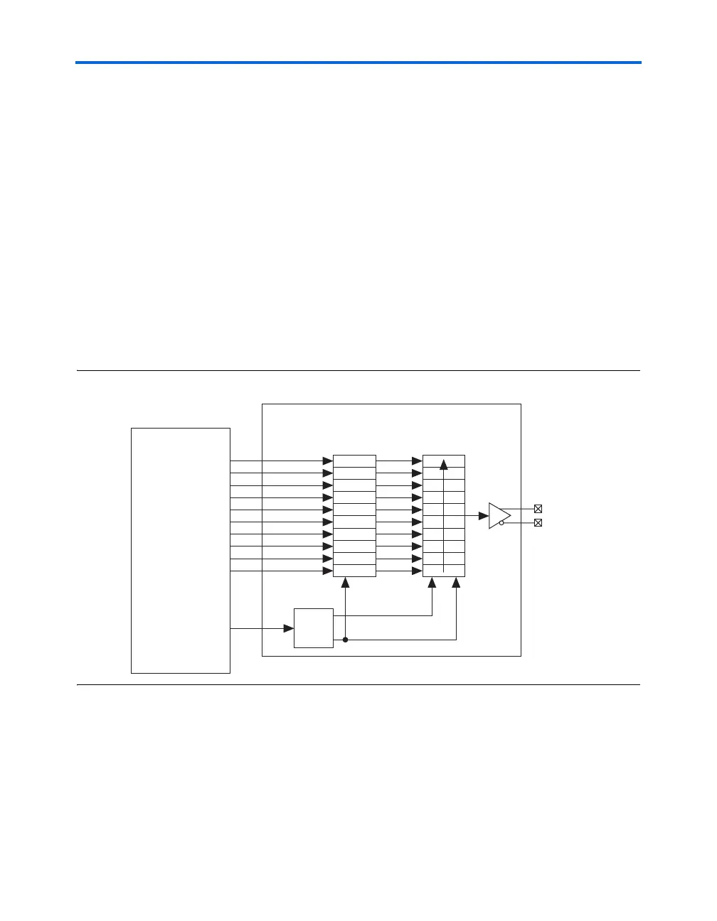
The logic array sends parallel data to the SERDES transmitter circuit
when the TXLOADEN signal is asserted. This signal is generated by the
high-speed counter circuitry of the logic array low-frequency clock’s
rising edge. The data is then transferred from the parallel register into the
serial shift register by the TXLOADEN signal on the third rising edge of the
high-frequency clock.
Figure 5–5 shows the block diagram of a single SERDES transmitter
channel and Figure 5–6 shows the timing relationship between the data
and clocks in Stratix devices in
×10 mode. W is the low-frequency
multiplier and J is the data parallelization division factor.
Figure 5–5. Stratix High-Speed Interface Serialized in ×10 Mode
PD9
PD8
PD7
PD6
PD5
PD4
PD3
PD2
PD1
PD0
PD9
PD8
PD7
PD6
PD5
PD4
PD3
PD2
PD1
PD0
Stratix
Logic Array
Transmitter Circuit
Parallel
Register
Serial
Register
Fast
PLL
TXOUT+
TXOUT−
×
W
TXLOADEN