6–22 Altera Corporation
Stratix Device Handbook, Volume 2 July 2005
Operational Modes
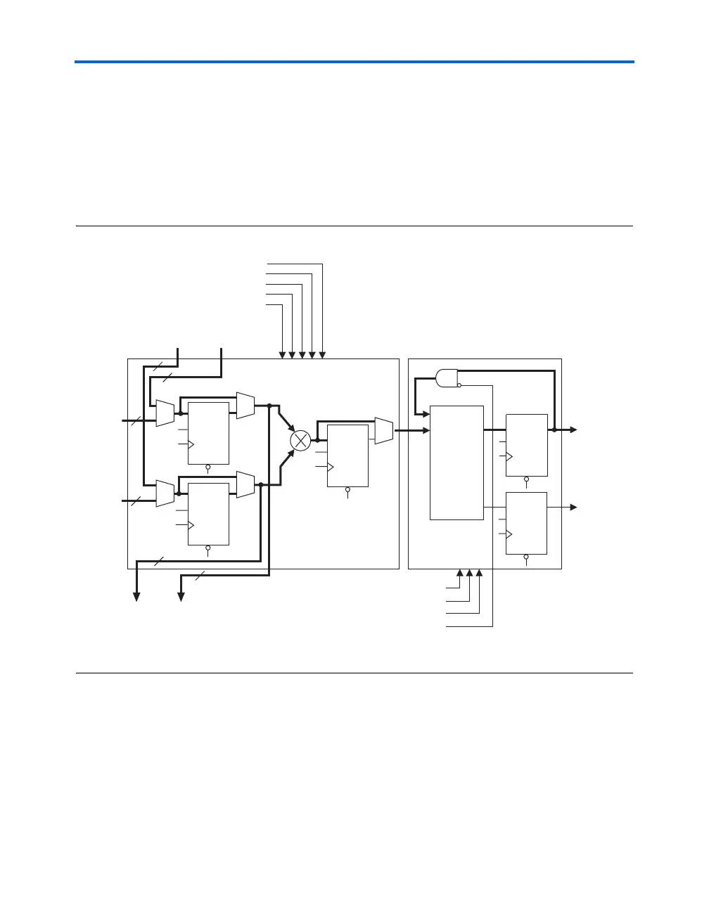
Multiply Accumulator Mode
In multiply accumulator mode, the output of the multiplier stage feeds
the adder/output block, which is configured as an accumulator or
subtractor (see Figure 6–12). You can implement up to two independent
18-bit multiply accumulators in one DSP block. The Quartus II software
implements smaller multiplier-accumulators by tying the unused low-
order bits of an 18-bit multiplier to ground.
Figure 6–12. Multiply Accumulator Mode
Note to Figure 6–12:
(1) The signa and signb signals are the same in the multiplier stage and the adder/output block.
The multiply accumulator output can be up to 52 bits wide for a
maximum 36-bit result with 16-bits of accumulation. In this mode, the
DSP block uses output registers and the accum_sload and overflow
signals. The accum_sload[1..0] signal synchronously loads the
multiplier result to the accumulator output. This signal can be
unregistered or registered once or twice. The DSP block can then begin a
new accumulation without losing any clock cycles. The overflow signal
indicates an overflow or underflow in the accumulator. This signal is
CLRN
D
Q
ENA
CLRN
D
Q
ENA
Data A
Data B
Data Out
overflow
shiftoutb shiftouta
shiftina
shiftinb
aclr
clock
ena
signa (1)
signb (1)
CLRN
D
Q
ENA
CLRN
D
Q
ENA
Accumulator
addnsub1
signa
signb
accum_sload1
CLRN
D
Q
ENA