1–52 Altera Corporation
Stratix Device Handbook, Volume 2 July 2005
Board Layout
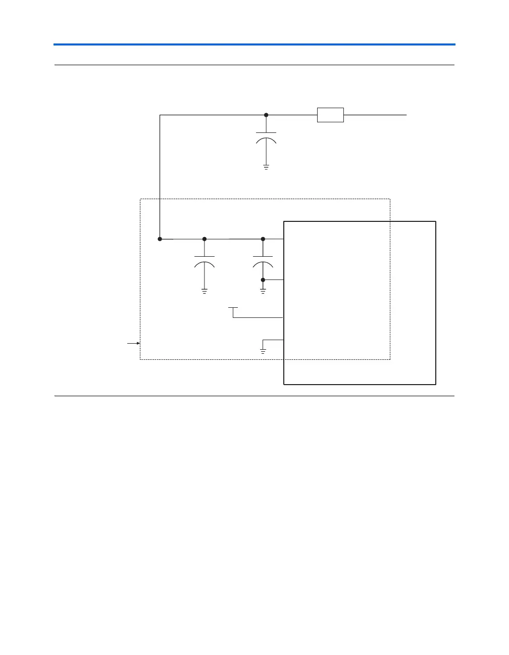
Figure 1–24. PLL Power Schematic for Stratix or Stratix GX PLLs
VCCG & GNDG
The guard ring power and ground pins are called
PLL<PLL number>_VCCG and PLL<PLL number>_GNDG. The guard ring
isolates the PLL circuit from the rest of the device. Connect these guard
ring V
CCG
pins to the quietest digital supply on the board. In most
systems, this is the digital 1.5-V supply supplied to the device's V
CCINT
pins. Connect the V
CCG
pins to a power supply even if you do not use the
PLL. You can connect the GNDG pins directly to the same ground plane as
the device’s digital ground. See Figure 1–24.
0.1 μF 0.001 μF
10 μF
Ferrite
Bead
1.5-V Suppl
Stratix Device
PLL<PLL number>_VCCA
PLL<PLL number>_GNDA
PLL<PLL number>_VCCG
PLL<PLL number>_GNDG
Repeat for Each PLL
Power and Ground Set
V
CCINT