Altera Corporation 11–21
July 2005 Stratix Device Handbook, Volume 2
Configuring Stratix & Stratix GX Devices
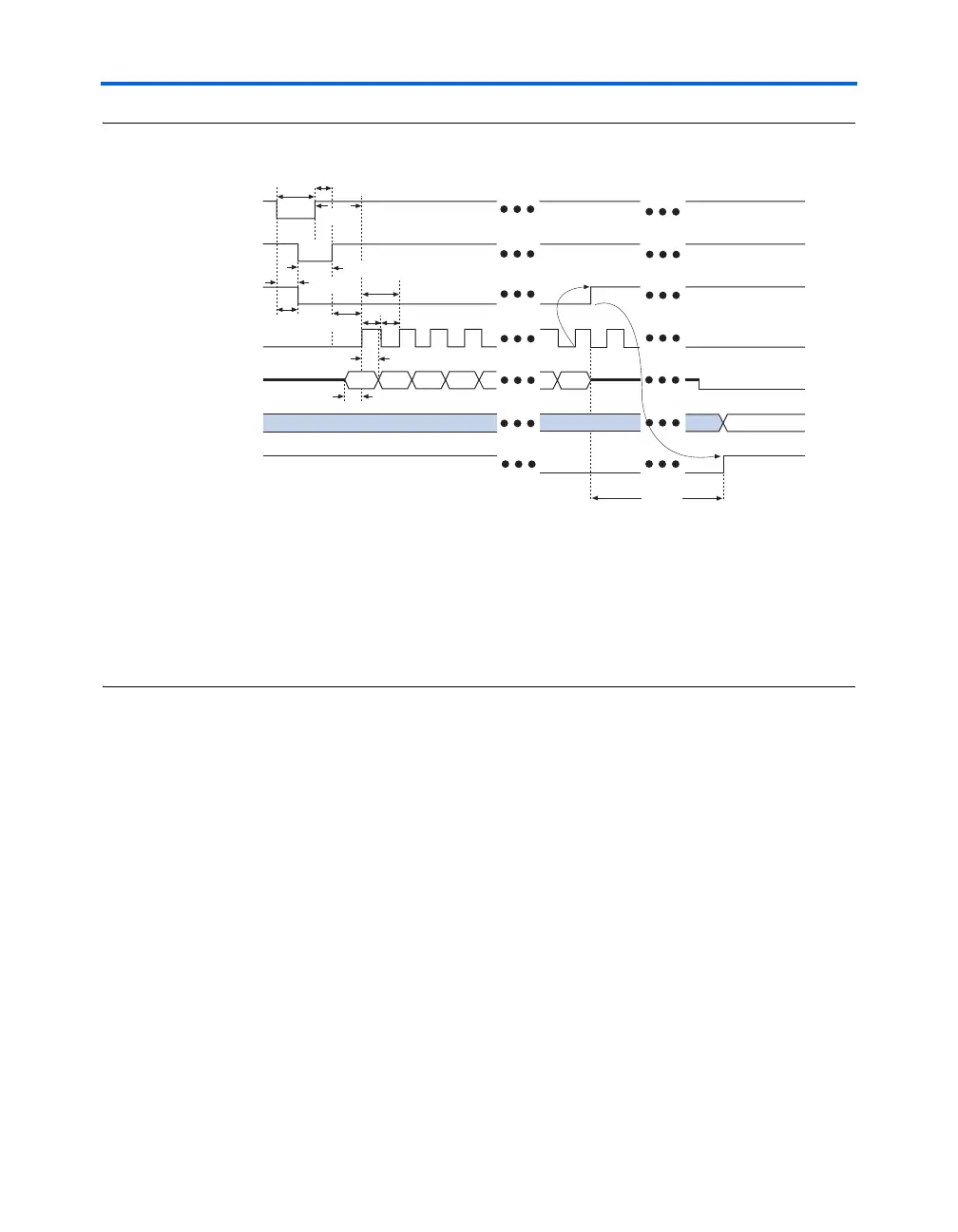
Figure 11–9. PS Timing Waveform for Stratix & Stratix GX Devices Note (1)
Notes to Figure 11–9:
(1) The beginning of this waveform shows the device in user-mode. In user-mode, nCONFIG, nSTATUS, and
CONF_DONE are at logic high levels. When nCONFIG is pulled low, a reconfiguration cycle begins.
(2) Upon power-up, the Stratix II device holds nSTATUS low for the time of the POR delay.
(3) Upon power-up, before and during configuration, CONF_DONE is low.
(4) DCLK should not be left floating after configuration. It should be driven high or low, whichever is convenient.
DATA[] is available as user I/Os after configuration and the state of these pins depends on the dual-purpose pin
settings.
FPP Configuration
Parallel configuration of Stratix and Stratix GX devices meets the
continuously increasing demand for faster configuration times. Stratix
and Stratix GX devices can receive byte-wide configuration data per clock
cycle, and guarantee a configuration time of less than 100 ms with a 100-
MHz configuration clock. Stratix and Stratix GX devices support
programming data bandwidth up to 800 megabits per second (Mbps) in
this mode. You can use parallel configuration with an EPC16, EPC8, or
EPC4 device, or a microprocessor.
This section discusses the following schemes for FPP configuration in
Stratix and Stratix GX devices:
■ FPP Configuration Using an Enhanced Configuration Device
■ FPP Configuration Using a Microprocessor
nCONFIG
nSTATUS (2)
CONF_DONE (3)
DCLK
DATA
User I/O
INIT_DONE
Bit 0 Bit 1
Bit 2
Bit 3 Bit n
t
CD2UM
t
CF2ST1
t
CF2CD
t
CFG
t
CH
t
CL
t
DH
t
DSU
t
CF2CK
t
STATUS
t
CLK
t
CF2ST0
t
ST2CK
High-Z
User Mode
(4)
(4)