Altera Corporation 4–27
June 2006 Stratix Device Handbook, Volume 2
Selectable I/O Standards in Stratix & Stratix GX Devices
Programmable Current Drive Strength
The Stratix and Stratix GX device I/O pins support various output
current drive settings as shown in Table 4–7. These programmable drive
strength settings help decrease the effects of simultaneously switching
outputs (SSO) in conjunction with reducing system noise. The supported
settings ensure that the device driver meets the I
OH
and I
OL
specifications
for the corresponding I/O standard.
These drive-strength settings are programmable on a per-pin basis (for
output and bidirectional pins only) using the Quartus II software. To
modify the current strength of a particular pin, see “Programmable Drive
Strength Settings” on page 4–40.
Hot Socketing
Stratix devices support hot socketing without any external components.
In a hot socketing situation, a device’s output buffers are turned off
during system power-up or power-down. Stratix and Stratix GX devices
support any power-up or power-down sequence (V
CCIO
and V
CCINT
) to
simplify designs. For mixed-voltage environments, you can drive signals
into the device before or during power-up or power-down without
damaging the device. Stratix and Stratix GX devices do not drive out until
the device is configured and has attained proper operating conditions.
Even though you can power up or down the V
CCIO
and V
CCINT
power
supplies in any sequence you should not power down any I/O bank(s)
that contains the configuration pins while leaving other I/O banks
powered on. For power up and power down, all supplies (V
CCINT
and all
V
CCIO
power planes) must be powered up and down within 100 ms of one
another. This prevents I/O pins from driving out.
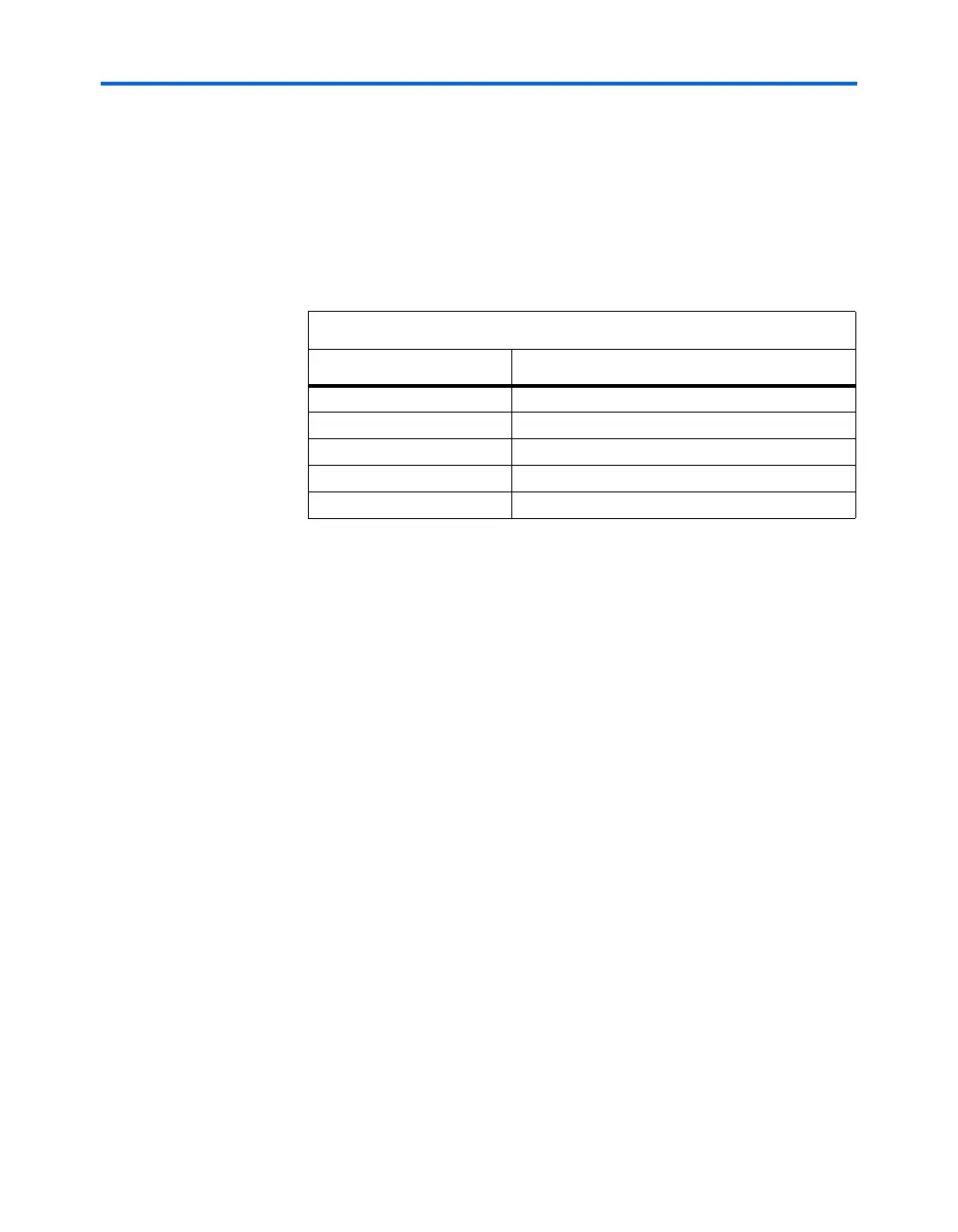
Table 4–7. Programmable Drive Strength
I/O Standard
I
OH
/ I
OL
Current Strength Setting (mA)
3.3-V LVTTL 24 (1), 16, 12, 8, 4
3.3-V LVCMOS 24 (2), 12 (1), 8, 4, 2
2.5-V LVTTL/LVCMOS 16 (1), 12, 8, 2
1.8-V LVTTL/LVCMOS 12 (1), 8, 2
1.5-V LVCMOS 8 (1), 4, 2
Notes to Ta b le 4 – 7 :
(1) This is the Quartus II software default current setting.
(2) I/O banks 1, 2, 5, and 6 do not support this setting.