1–28 Altera Corporation
Stratix Device Handbook, Volume 2 July 2005
Enhanced PLLs
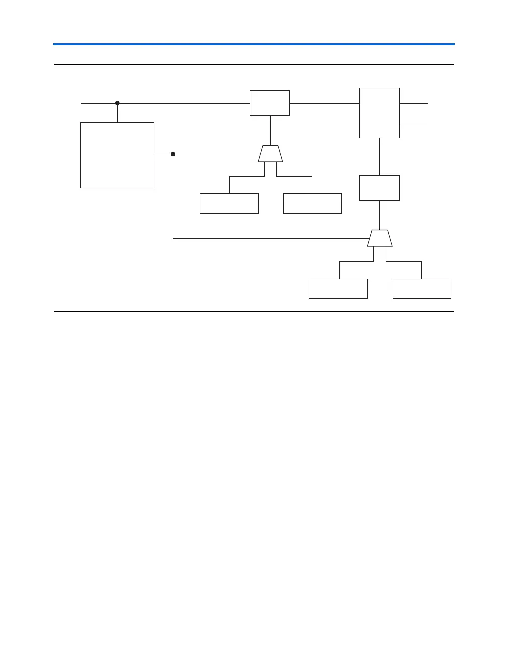
Figure 1–15. Spread-Spectrum Circuit Block Diagram
Figure 1–16 shows a VCO frequency waveform when toggling between
different counter values. Since the enhanced PLL switches between two
different m and n values, the result is a straight line between two
frequencies, which gives a linear modulation. The magnitude of
modulation is determined by the ratio of two m/n sets. The percent
spread is determined by:
percent spread = (f
VCOmax
− f
VCOmin
)/f
VCOmax
= 1 − [(m
2
× n
1
)/(m
1
× n
2
)]
The maximum and minimum VCO frequency is defined as:
f
VCOmax
= (m
1
/n
1
) × f
ref
f
VCOmin
= (m
2
/n
2
) × f
ref
÷ n
n count1
n count2
PFD
Up
Down
Spread
Spectrum
Counter
÷ m
m count1
m count2
refclk