9. General operation example
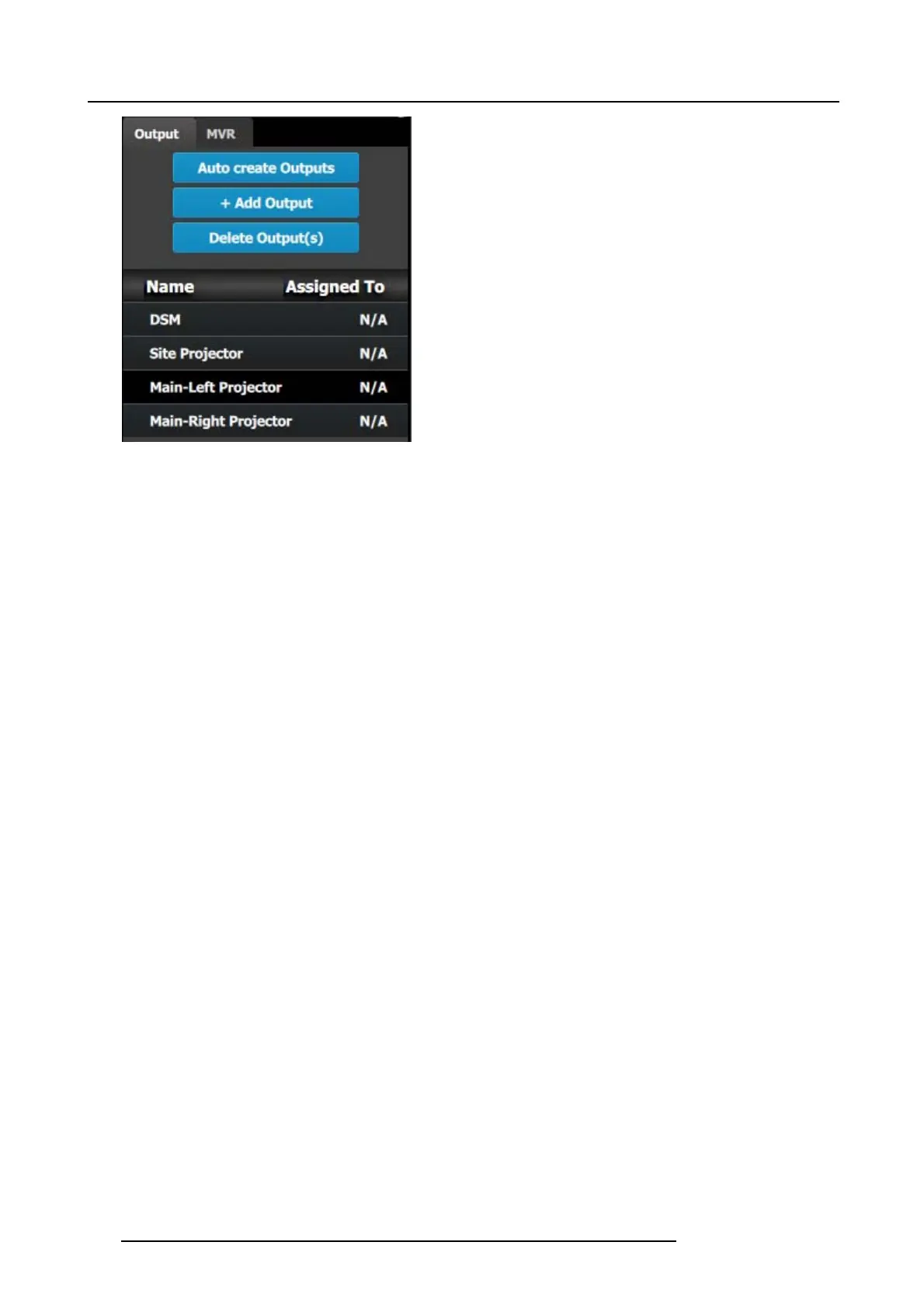
Image 9-8
Note: The “N/A” at this end refers to the destinations that will be added next.
C5 – Part1: Add Site Screen Destinations
In this section we will create the S ite Screen Destination and assign two layers.
1. Click on the Destination tabtodefine destinations for the creat
ed outputs.
2. From the diagram area click on the first BNC of slot 13 that is the Site Projector output connector. The BNC will be highlighted.
3. Click o n the +Add Screen Destination blue button to assign the output for the screen destination.
4. When the de stination is created a box appears next to the E2 diagram.
5. Double click on the Destination1 area in the Nam e list to edit the name.
6. When the area turns blue, click the er aser icon to clear the field and type a new name, “Site Screen”.
7. Click on the top at the Adjust:Site Screen tab and in the Assign menu under the Output section c lick on the +Assign Layer to
Destination blue button to as sign a layer to the destination .
8. In the layout area “1 layer” will appear in the green area of the box.
9. Repeat the previous step to add one more layer.
C5 – Part2: Add Main Screen Destinations
In this section w e will create the M ain Sc reen Destinations and as sign 3 layers.
1. To c reate the Main Screen destination, please repeat steps 2 thru 6 of the p revious stage (C5–Par t1) by first clicking on the
“Main-Left Projector” BNC.
2. Rename the destination to “Main Sc reen”.
3. After the des tination is cre ated, click on the “Main-Right P rojector” B NC and drag it into the “Main Screen” destination box. The
Screen size will immediately change to 3840x1080.
4. Repeat the same s teps as abov e to add layer to the destination b ut click the add button 3- times to add 3 layers.
C5 – Part3: adjust the projector overlap in Main Screen destinations
In this section we will adjust the projector overlap area for the M ain sc reen.
1. Under the Wide m enu in the small diagram area sho ws the destination, click on the line between the two sites. The line turns
blue.
2. Click on the Data Double button and enter “100” for the H overlap value. Note: We w ill leave the feathering to the defau lt value
of 2.2.
196
R5905948 E2 12/12/2014