6. GUI orientation
by default names inputs as “Input 1, 2, 3… .” . Input configuration names can be renamed by double-clicking on the name and turning
the box blue.
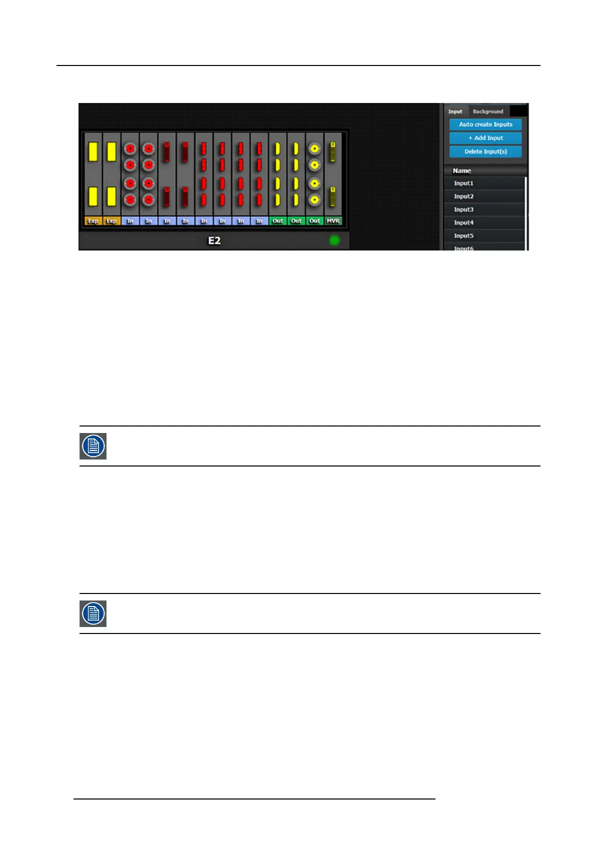
Image 6-17
The auto create feature only creates 2K input. 3D an d 4K Inputs need to be assigned manually. S ee How to add Input section
below.
How to add Input
Inputs configurations c an be added manually to un-assigned connectors.
1. Click on the Add Input bu tton.
The A dd Input butto n is replaced by the Done Adding button (highlighted in blue).
2. In the S ystem diagram area, c lick on the connector(s) that need to be assigned.
Note: If the input signal is 4K provided by the 4 SDI connectors, 4 SDI connectors need to be selected.
Connector(s) is immediately highlighted in blue.
3. The selection is completed by clicking the Do ne Add ing button that is highlighted in blue.
A new Input is added in the input list.
To stop the add procedure without add new input, just click on the Done A dding button without selecting an
input.
How to delete Input
1. Click on the Delete Input(s ) button
The D e l e te Input(s ) b utton is replaced by the Delete Selected button (highlighted in red).
2. Click on the corresponding connector in the graphical area.
Or,
click in the “x” on the right hand side in the input con figura tion list.
Connector(s) is immediately highlighted in blue.
3. The deletion is completed by clicking the Delete Selected button.
Multiple connector configurations can be selected to be deleted together.
How to access to the Input c onfiguration adjustments
Adjustments to inputs are performed in the “Adjust” panel:
1. Select the input from the configuration list
Or,
clicking on the connector graphic.
An input is selec ted.
2. Click on the Adjust tab that is on the top of the Adjustment area.
86
R5905948 E2 12/12/2014