Ê Run the two 4-conductor cables with white 4-pin connectors towards the
drive cages and connect them to up to two SAS backplanes (see orange
arrow).
Ê Run the two 6-conductor cables with black 6-pin connectors along the power
backplanes and through the cable clamps as shown (see blue arrows).
Concluding steps
Ê Mount the system board carrier as described in section "Installing the
system board carrier" on page 88.
V CAUTION!
Ensure not to trap or pinch any cables running through the cable exit
from the power backplane.
Ê Reinstall the system board as described in section "Installing the system
board" on page 691.
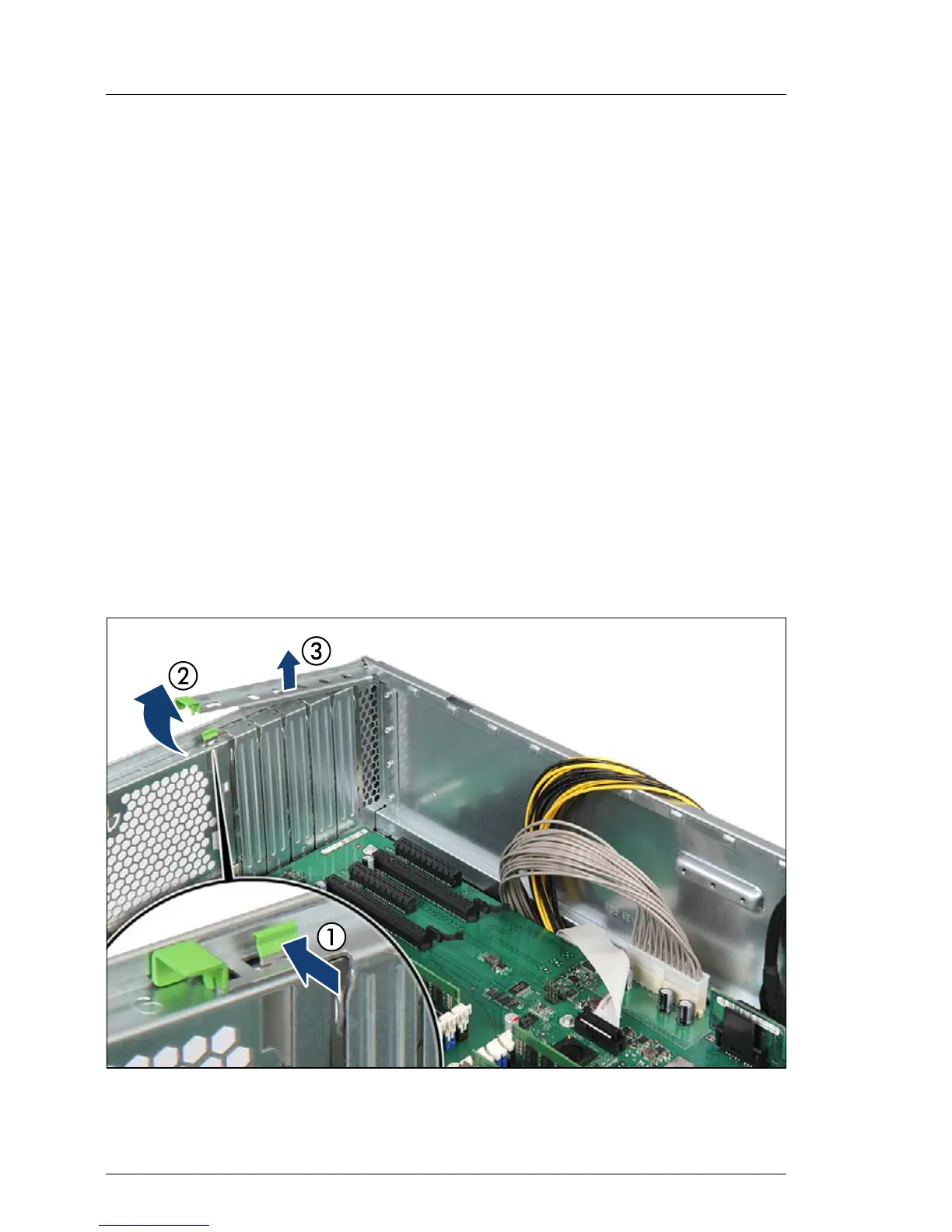
9.4.2.4 Removing PCI slot brackets
Figure 270: Removing the PCI slot bracket (A)
 Loading...