JUNOS Internet Software Network Operations Guide: Hardware
144 ! Monitoring the Routing Engine Status
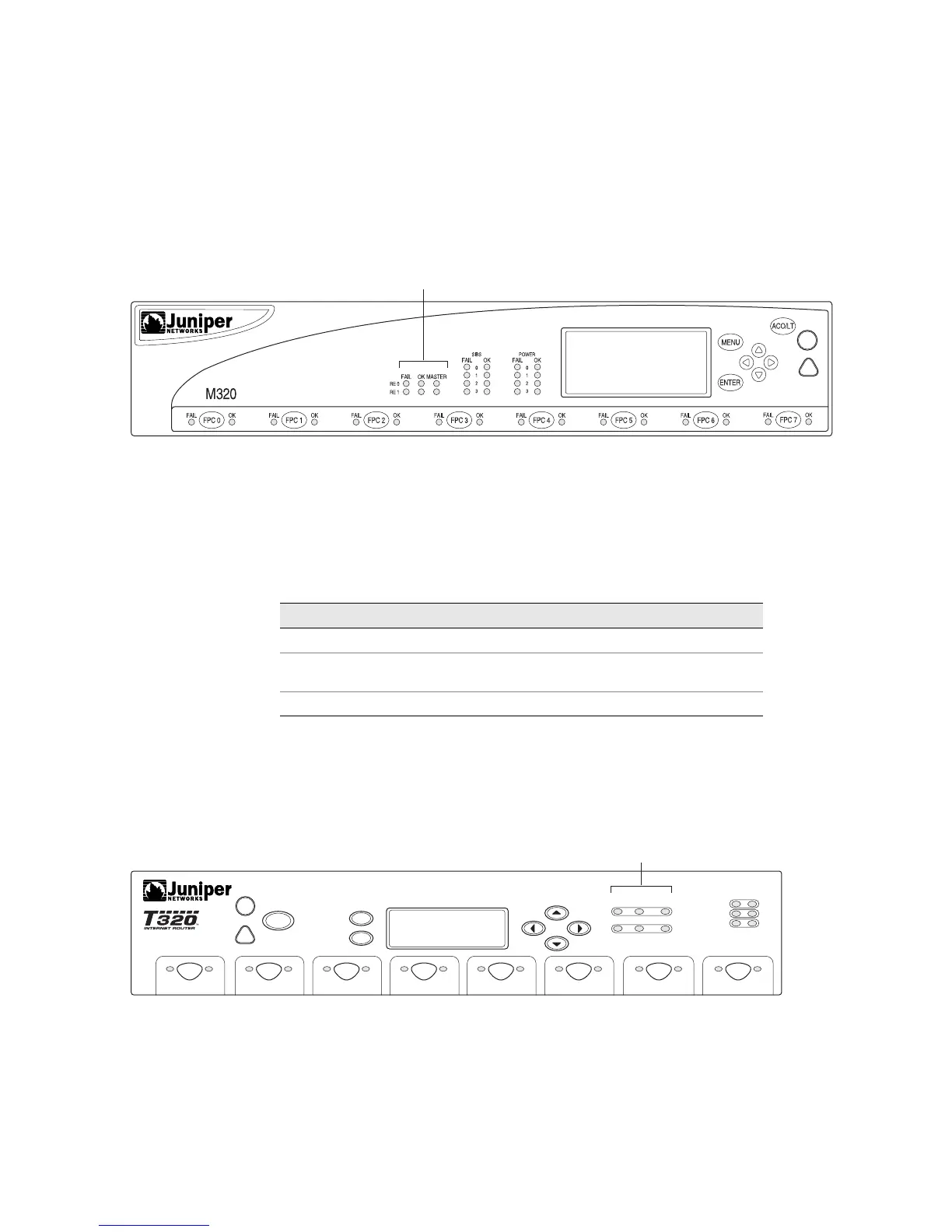
Check the M320 Router Routing Engine LEDs
Figure 49 shows the host module LEDs on the M320 router craft interface.
Figure 49: M320 Router Redundant Host Module LEDs
Each host subsystem has three LEDs, located in the middle of the craft interface,
that indicate status. The LEDs labeled
RE0 show the status of the Routing Engine in
slot
RE0 and the Control Board in slot CB0. The LEDs labeled RE1 show the status of
the Routing Engine in slot
RE1 and the Control Board in slot CB1. Table 40 describes
the functions of the host subsystem LEDs.
Table 40: M320 Router Host Subsystem LEDs
Check the T320 Router Routing Engine LEDs
Figure 50 shows the host module LEDs on the T320 router craft interface.
Figure 50: T320 Router Redundant Host Module LEDs
Each host subsystem has three LEDs, located on the upper right of the craft
interface, which indicate status. The LEDs labeled HOST0 show the status of the
Routing Engine in slot RE0 and the Control Board in slot CB0. The LEDs labeled
HOST1 show the status of the Routing Engine in slot RE1 and the Control Board in
slot CB1.
g003294
Routing Engine LEDs
Label Color State Description
FAIL Red On steadily Host module is offline.
OK Green On steadily Host module is online and functioning
normally.
MASTER Green On steadily Host module is functioning as master.
g003295
SP0
SP1
SP2
ACO/LT
ENTER
MENU
HOST0
HOST1
FAIL OK
MASTER
FAIL OK
MASTER
FAIL OK
FPC 0
OKFAIL OKFAIL OKFAIL OKFAIL OKFAIL OKFAIL OKFAIL OKFAIL
FPC 1 FPC 2
FPC 3
FPC 4 FPC 5 FPC 6 FPC 7
Host subsystem LEDs