Monitoring the Routing Engine Status ! 145
Chapter 14: Monitoring the Routing Engine
Table 41 describes the functions of the host subsystem LEDs.
Table 41: T320 Router Host Subsystem LEDs
Check the T640 Routing Node Routing Engine LEDs
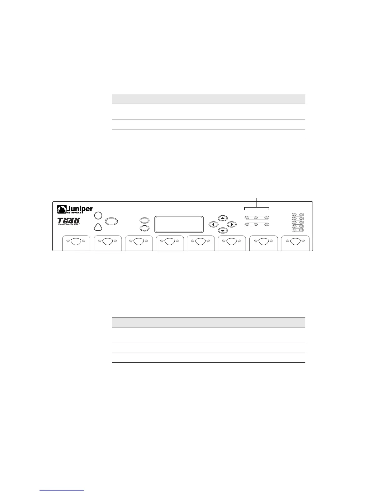
Figure 51 shows the host module LEDs on the T640 routing node craft interface.
Figure 51: T640 Routing Node Redundant Host Module LEDs
Each host subsystem has three LEDs, located on the upper right of the craft
interface, which indicate status. The LEDs labeled HOST0 show the status of the
Routing Engine in slot RE0 and the Control Board in slot CB0. The LEDs labeled
HOST1 show the status of the Routing Engine in slot RE1 and the Control Board in
slot CB1. Table 42 describes the functions of the host subsystem LEDs.
Table 42: T640 Routing Node Host Subsystem LEDs
Label Color State Description
OK Green On steadily Host module is online and functioning
normally.
FAIL Red On steadily Host module is offline.
MASTER Green On steadily Host module is functioning as master.
g003296
SP0
SP1
SP2
SP3
SP4
ACO/LT
ENTER
MENU
HOST0
HOST1
FAIL OK
MASTER
FAIL OK
MASTER
FAIL OK
FPC 0
OKFAIL OKFAIL OKFAIL OKFAIL OKFAIL OKFAIL OKFAIL OKFAIL
FPC 1 FPC 2
FPC 3
FPC 4 FPC 5 FPC 6 FPC 7
Host subsystem LEDs
Label Color State Description
OK Green On steadily Host module is online and functioning
normally.
FAIL Red On steadily Host module is offline.
MASTER Green On steadily Host module is functioning as master.