Understanding Redundant Cooling System Components ! 527
Chapter 39: Monitoring Redundant Cooling System Components
M10i Router Redundant Cooling System Components
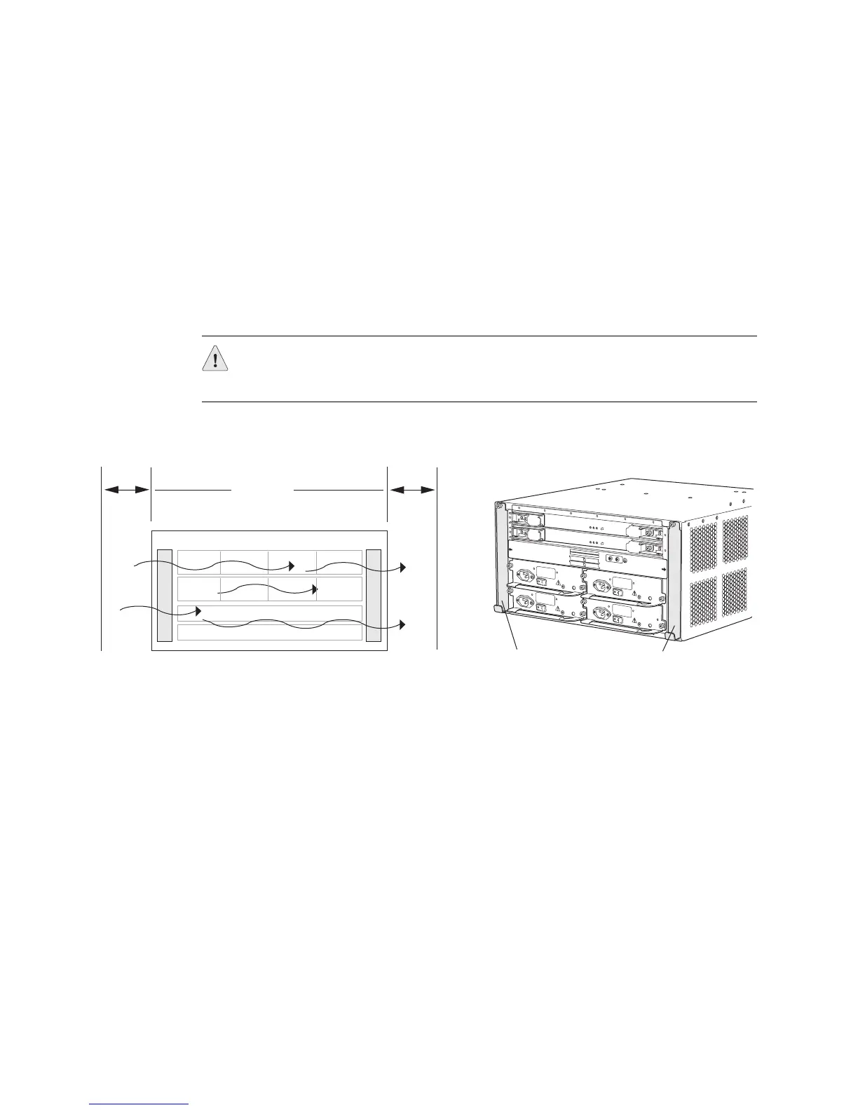
The M10i router cooling system consists of two fan trays, located along the left and
right side of the chassis, that provide side-to-side cooling (see Figure 211). They
connect directly to the router midplane. Each fan tray is a single unit containing
eight individually fault-tolerant fans. If a single fan fails, the remaining fans continue
to function indefinitely. For proper airflow, the primary fan tray should be installed
in slot
1 (the left slot looking at the chassis from the rear) and must be installed for
proper cooling at all times. The redundant fan tray, if present, should be installed in
slot
0 on the right. This fan tray provides additional cooling and redundancy. The
fan tray is hot-removable and hot-insertable.
Figure 211: M10i Router Cooling System Components and Airflow
M20 Router Redundant Cooling System Components
The M20 router cooling system includes:
! Three front fan trays—Cool the Flexible PIC Concentrators (FPCs) and the
System and Switch Board (SSB). These fan trays are located on the left front
side of the chassis.
! One rear fan tray—Cools the Routing Engine. This fan tray is located
immediately to the right of the Routing Engine.
! Power supply integrated fan—A built-in fan cools each power supply.
The four fan trays plug directly into the router midplane and work together to
provide side-by-side cooling.
CAUTION: Do not remove both fan trays for more than one minute while the
router is operating. The fans are the sole source of cooling, and the router will
overheat when they are absent.
FANTR AY O
FANTRAY 1
N
O
T
E
:
C
-
F
E
B
0
C
-
F
E
B
1
P/S 3
P/S 2
P/S 1
P/S 0
P
/
S
0
A
N
D
P
/
S
1
M
U
S
T
B
E
P
R
E
S
E
N
T
F
O
R
N
O
R
M
A
L
O
P
E
R
A
T
I
O
N
.
g003282
Slot 2 Redundant
fan tray
Rear of chassis
Front of chassis
Slot 1 Primary
fan tray
6" (15.2 cm)
for airflow
(recommended)