JUNOS Internet Software Network Operations Guide: Hardware
528 ! Understanding Redundant Cooling System Components
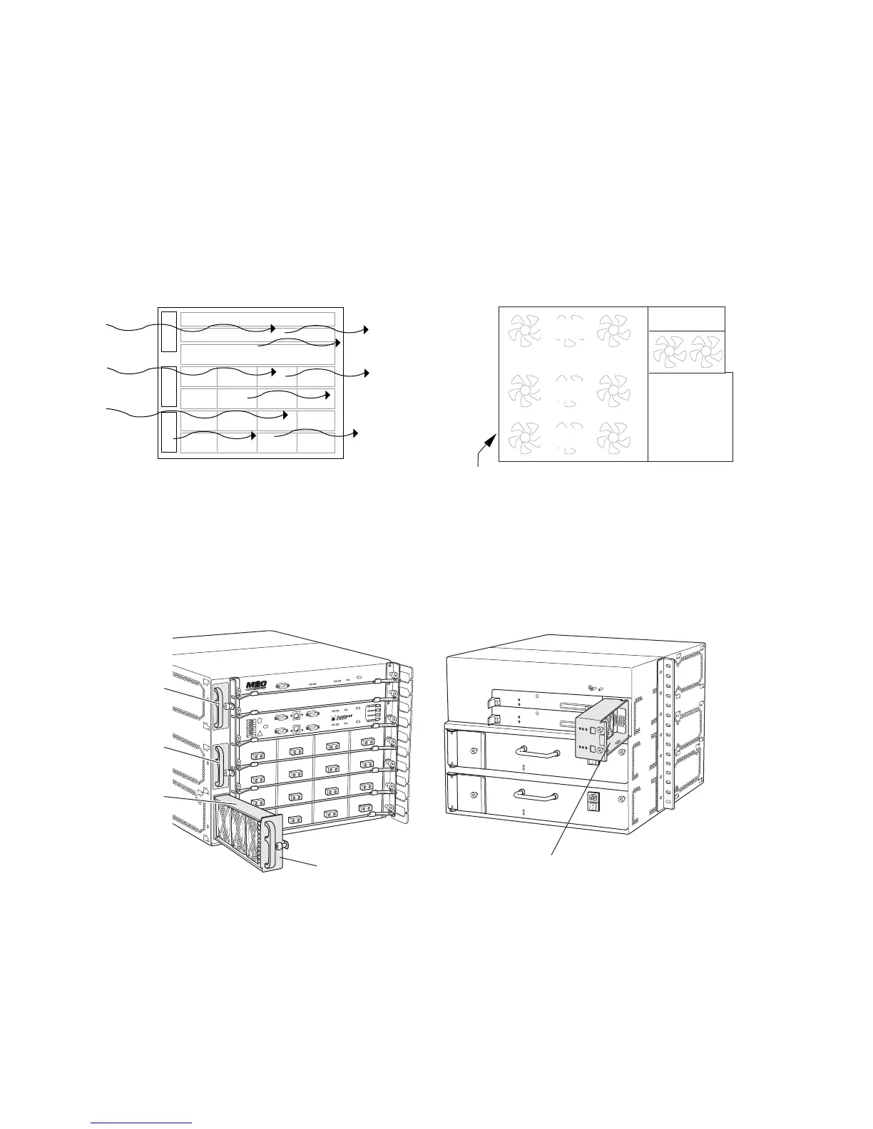
The fans operate in unison to maintain an acceptable operating temperature for the
Routing Engine and midplane. Each cooling subsystem maintains a separate
airflow, and each is monitored independently for temperature control. Figure 212
shows the M20 router cooling system components and airflow.
Figure 212: M20 Router Cooling System and Airflow
Both front and rear fan trays are hot-removable and hot-insertable. You can remove
and replace these components without powering down the system and disrupting
routing functions. Figure 213 shows the M20 router cooling system components.
Figure 213: M20 Router Cooling System Components
Front fan trays
Front of router
Rear fan tray
Side of chassisFront of chassis
Fan
Fan
Fan
Craft interface display
SSB
SSB
PIC PIC PIC PIC
PIC PIC PIC PIC
PIC PIC PIC PIC
PIC PIC PIC PIC
1769
Upper fan
Middle fan
Bottom fan
g001770
Front fan tray(s)
Upper fan
Middle fan
Bottom fan
RearFront
Rear fan tray