JUNOS Internet Software Network Operations Guide: Hardware
256 ! Understanding the Cooling System
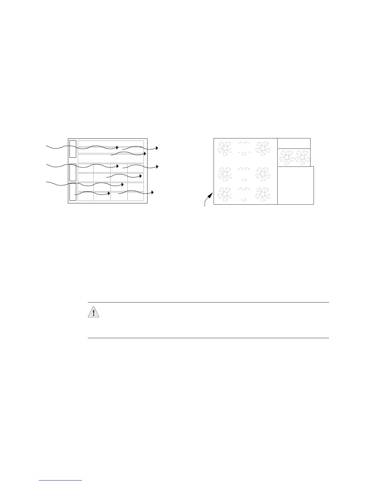
The cooling system includes several fan trays that draw room air into the chassis to
keep its internal temperature below a maximum acceptable level. The cooling
subsystems have redundant components, which are controlled by the SSB. If a fan
fails, the remaining fans provide sufficient cooling for the unit indefinitely (see
Figure 109.
Figure 109: M20 Router Cooling System and Airflow
M40 Router Cooling System
The M40 router cooling system consists of the following components:
! Air intake vent and air filter (see Figure 111 on page 257)—Provide an opening
for room air to enter the router. They are located at the bottom of the chassis
front, below the craft interface. The air filter prevents dust and other particles
from entering the cooling system. For replacement instructions, see the M40
router hardware guide.
! Upper and lower impeller assemblies (see Figure 110 on page 257)—Cool the
Packet Forwarding Engine components (backplane, SCB, FPCs, and PICs). The
lower impeller assembly is located behind the craft interface at the front the
chassis, and the upper assembly is located above the fan tray at the rear of the
chassis. Each assembly houses two impellers for redundancy. The assemblies
are not interchangeable. For replacement instructions, see the M40 router
hardware guide.
! Fan tray (see Figure 111 on page 257)—Cools the Routing Engine and
backplane. The tray houses three fans for redundancy and is located above the
Routing Engine at the upper rear of the chassis. For replacement instructions,
see “Maintain and Replace the Fan Tray” on page 155.
! Power supply integrated fan—Cools the power supply. It is not field-replaceable.
Front fan trays
Front of Router
Rear fan tray
Side of chassisFront of chassis
Fan
Fan
Fan
Craft interface display
SSB
SSB
PIC PIC PIC PIC
PIC PIC PIC PIC
PIC PIC PIC PIC
PIC PIC PIC PIC
1769
Upper fan
Middle fan
Bottom fan
CAUTION: Do not remove the air filter for more than a minute while the router is
operating. The fans and impellers are powerful enough to draw in foreign material,
such as bits of wire, through the unfiltered air intake, which could damage router
components.