Understanding Redundant Cooling System Components ! 531
Chapter 39: Monitoring Redundant Cooling System Components
M40e and M160 Router Redundant Cooling System Components
The M40e and M160 routers include the following cooling system components:
! Front cooling subsystem—Cools the FPCs, PICs, and midplane. It includes a fan
tray located behind the cable management system and a large, central impeller
behind the craft interface (fan tray front left, fan tray front right, fan tray rear
left, fan tray rear right, and front top blower).
! Rear cooling subsystem—Cools the Switching and Forwarding Modules (SFMs),
host module, PFE Clock Generators (PCGs), and power supplies. It includes one
impeller located at the upper right of the chassis rear and another at the lower
left, as shown in Figure 217 (rear top blower and rear bottom blower). The
upper and lower impellers are not interchangeable.
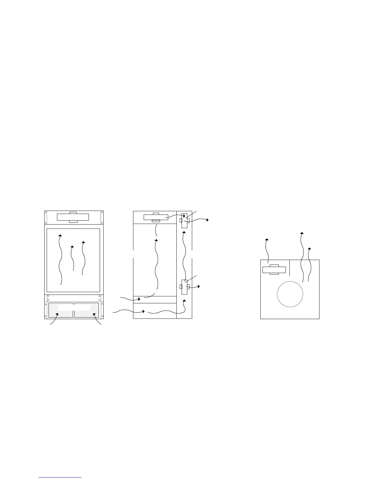
Figure 217 shows the M40e and M160 router cooling system components and
airflow.
Figure 217: M40e and M160 Router Cooling System and Airflow
Side view
Front
Rear
Front view
Top view
Impeller
Impeller
(upper front)
Impeller
Card cage
Fan tray
Impeller
1778
Front
Rear
(upper rear)
Air intake cover
Rear top blower
Rear bottom blower