Understanding the Cooling System ! 261
Chapter 19: Monitoring the Cooling System
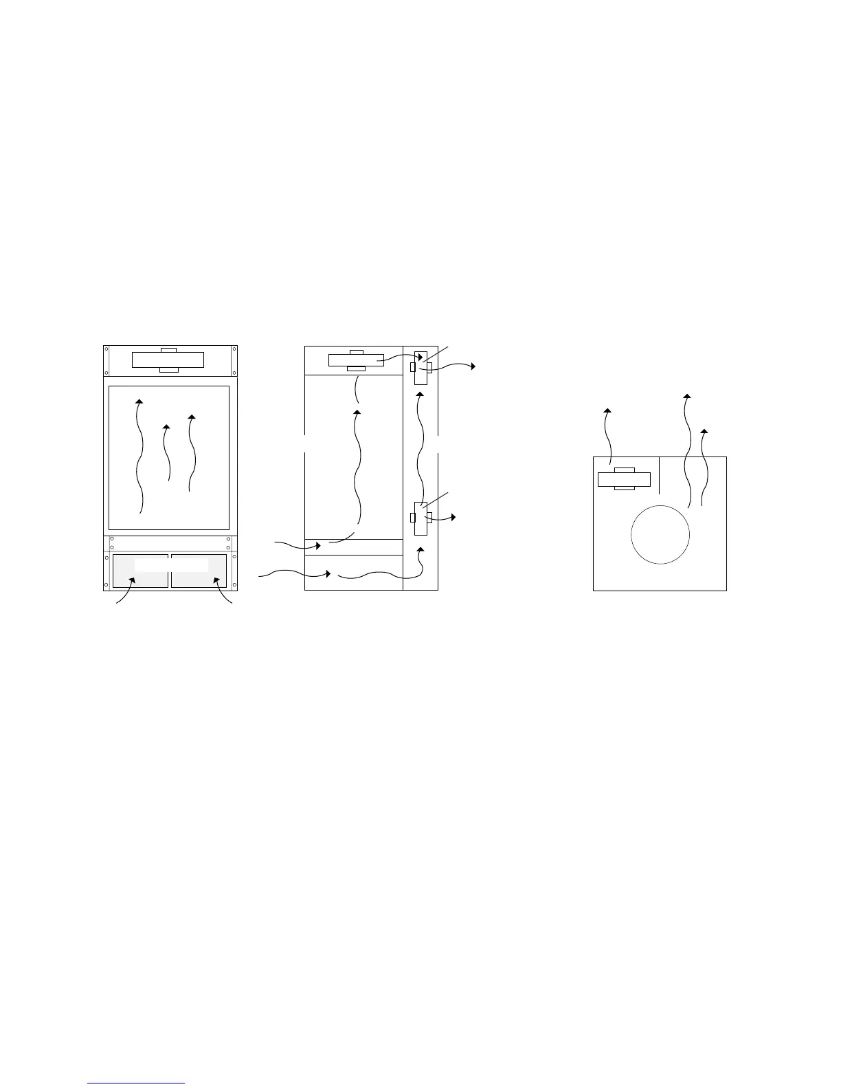
The cooling system draws in room air through the air intake vent located at the
front of the chassis below the cable management system. After entering the
chassis, the air stream separates into separate flows for the front and rear
subsystems, and the Miscellaneous Control Subsystem (MCS) monitors the
temperature of each flow independently.
Figure 114 shows the M40e and M160 router cooling system components and
airflow.
Figure 114: M40e and M160 Router Cooling System and Airflow
M320 Router Cooling System
The M320 cooling system consists of the following components (see Figure 115 on
page 262):
! Two front fan trays—The front fan trays each contain four fans and are
interchangeable. The front fan trays cool the components installed in the FPC
card cage (the FPCs, PICs, Connector Interface Panel [CIP], and midplane).
! Rear fan tray—The rear fan tray contains seven fans and is not interchangeable
with the front trays. The rear fan tray cools the components installed in the rear
card cage (the Routing Engines, Control Boards, and the Switch Interface
Boards [SIBs]).
! Front and rear air filter—Air filters for both the front and rear fan trays help
keep dust and other particles from entering the cooling system.
! Power supply fans—Each power supply has two fans that cool that power
supply.
Side view
Front
Rear
Front view
Top view
Impeller
Impeller
(upper front)
Impeller
Card cage
Fan tray
Impeller
1778
Front
Rear
(upper rear)
Air intake cover
Rear top blower
Rear bottom blower