Abb. Pin
Sin/Cos and
TTL
Sin/Cos
absolute
encoder,
SSI/EnDat
Absolute
encoder,
EnDat
(digital)
Absolute
encoder,
HIPERFACE®
5 4 3 2 1
10 9 8 7 6
15 14 13 12 11
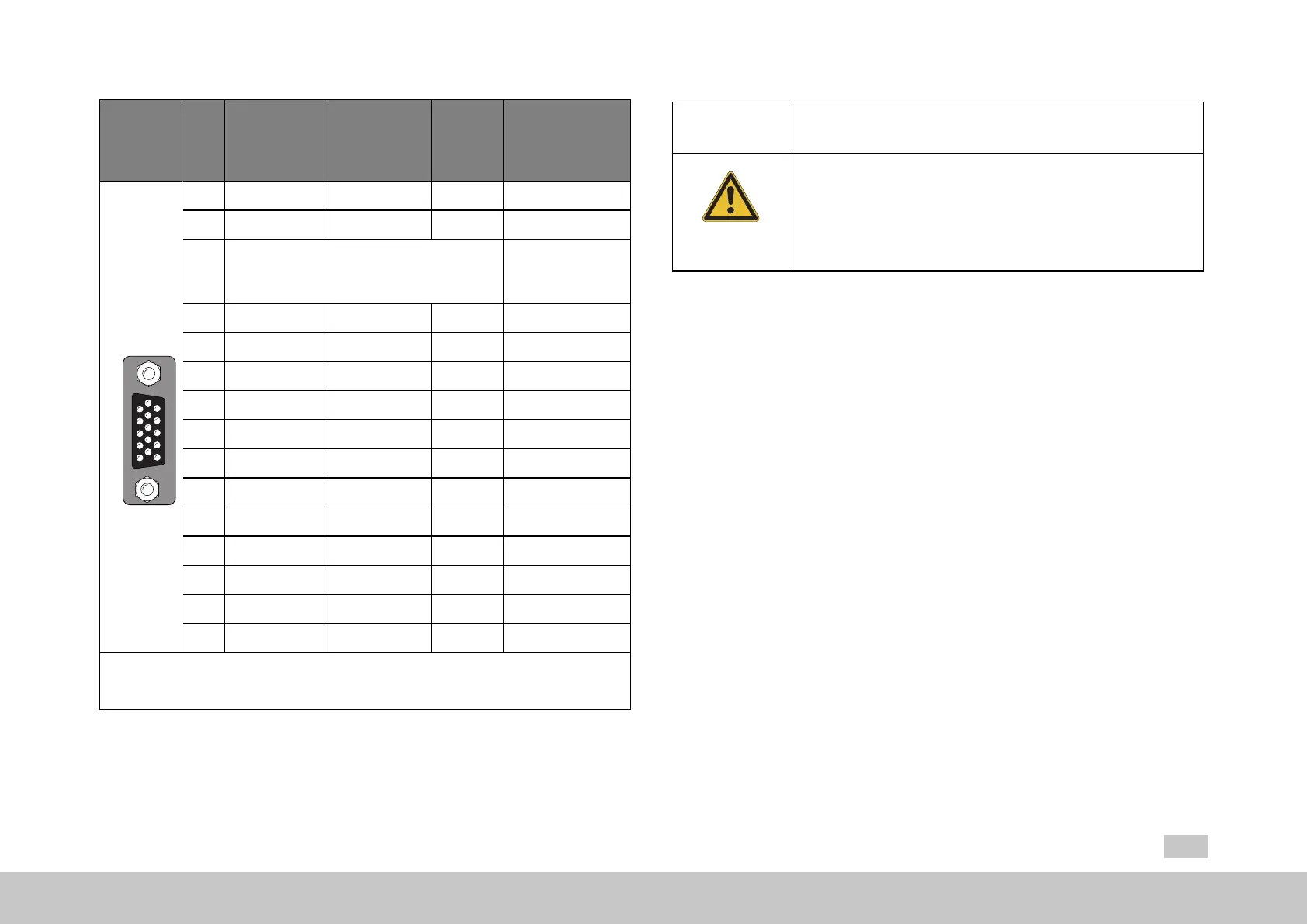
X7
Encoder
1 A- A- - REFCOS
2 A+ A+ - +COS
3
+5VDC±5%,IOUTmaximum=250mA
(150mAforhardwareversions0–1),
monitoringviasensorcable
1)
7to12V(typ.
11V)maximum
100mA
1)
4 - Data+ Data+ Data+
5 - Data- Data- Data-
6 B- B- - REFSIN
7 - - - U
S
-Switch
2)
8 GND GND GND GND
9 R- - - -
10 R+ - - -
11 B+ B+ - +SIN
12 Sense+ Sense+ Sense+ U
S
-Switch
2)
13 Sense- Sense- Sense- -
14 - CLK+ CLK+ -
15 - CLK- CLK- -
1) The total of the currents drawn at X7/3 and X6/4 must not exceed the specified
value!
2) After connecting pin 7 to pin 12, a voltage of 11.8 V will appear at X7, pin 3!
Table 6.3: Pin assignment X7 (MSD Servo Drive)
MOOG
ID
No.: CB40859-001 Date: 02/2018
MSD Servo Drive- Device Help
55
6 Encoder
CAUTION! Damage to the device as a result of incorrect motor winding
insulation!
Improper conduct can lead to damage to the motor/device.
l Themotortemperaturesensormusthavebasic
insulationtothemotorwindingwhenconnectedtoX5
andreinforced insulationtoEN61800-5-1when
connectedtoX6orX7.

 Loading...