278
Chapter5 Mounting
F3SG-SR
User’s Manual
Wiring and Installation
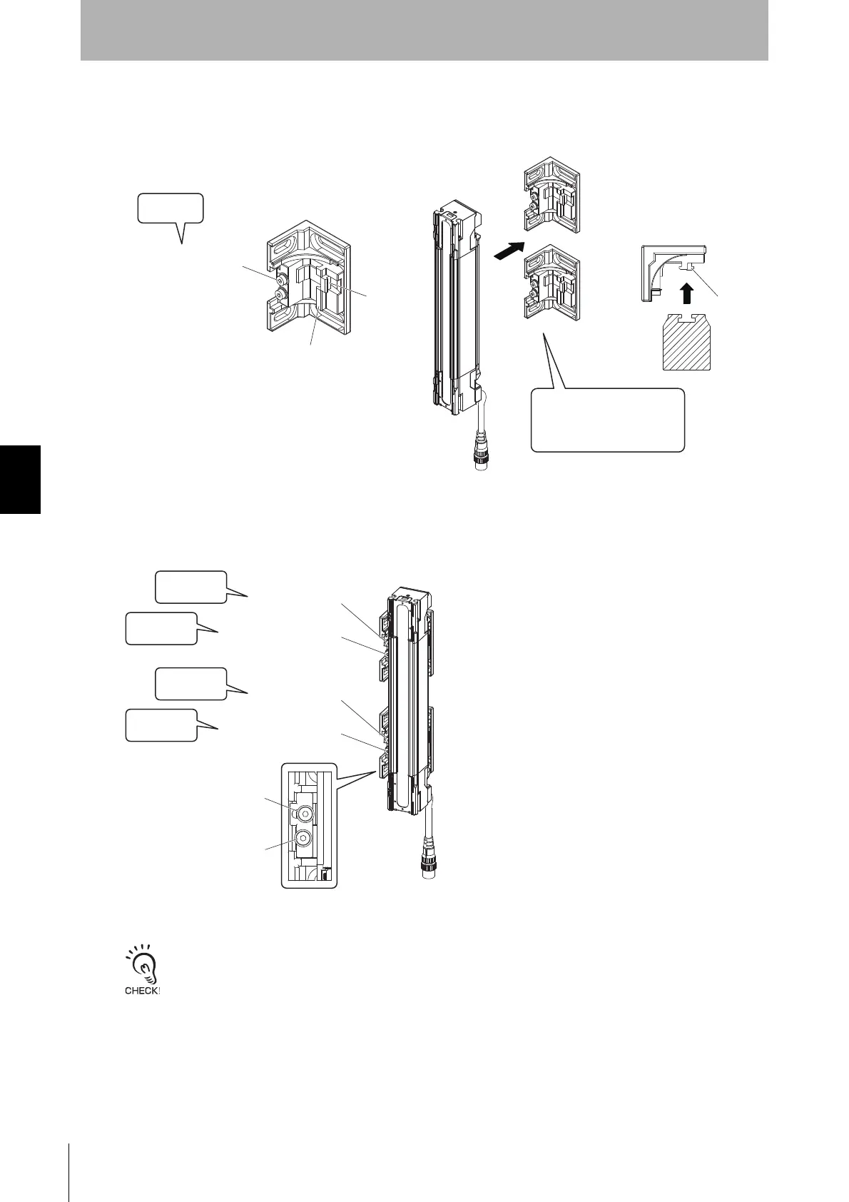
2. Fully loosen the Mounting Screws (hexagon socket head cap screw (M4×22)). Fit the Brackets (1) and
(2) to the backside of the sensor housing so that the groove of the backside of the housing receives the
hooks of the Brackets (1) and (2). (Fig. 2)
3. Securely tighten the Mounting Screws to fix the Adjustable Side-Mount Bracket to the sensor housing.
The recommended torque to tighten the Mounting Screws is 3.0 N•m. Then loosen the Alignment
Screws (hexagon socket head cap screws (M4×22)). (Fig. 3)
Tightening screws with a torque that considerably exceeds the recommended torque may cause failure.
Mounting Screw
(hexagon socket head
cap screw (M4×22))
Fit the hooks of Adjustable
Side-Mount Brackets to the
groove of the backside of
the housing
Loosen
Bracket (1)
Bracket (2)
Hook
Fig. 2
AlignmentScrew
(hexagonsockethead
capscrew(M4×22))
MountingScrew
MountingScrew
AlignmentScrew
(hexagonsockethead
capscrew(M4×22))
MountingScrew
AlignmentScrew
2.Loosen
1.Securely
tighten
2.Loosen
1.Securely
tighten
Fig. 3

 Loading...


