279
F3SG-SR
User’s Manual
Chapter5 Mounting
Wiring and Installation
E
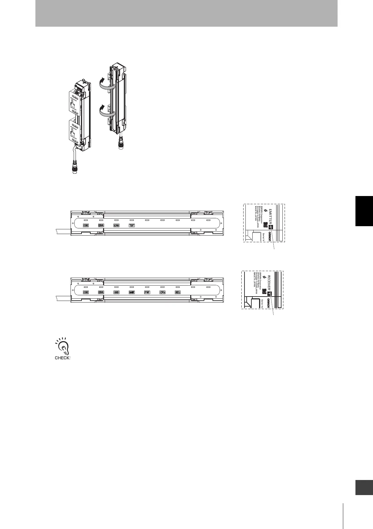
4. Power the emitter and receiver on to perform beam alignment.
For more information on the beam alignment procedure, refer to 5-3-5. Beam Alignment Procedure.
- The angle adjustment range of the Adjustable Side-Mount Brackets is ±15°.
- The ABI indicators are for the F3SG-SRA only. The TOP and BTM indicators are for the F3SG-SRB only.
- The ABI indicators of both emitter and receiver are illuminated in the case the Wired Synchronization is enabled. Only
the ABI indicators of the receiver are illuminated in the case the Optical Synchronization is enabled.
- It is recommended to use the Light Level Monitoring with the SD Manager 3 for beam alignment. Refer to Chapter 4
Setting with SD Manager 3 for more information.
- The ABI indicators (green) will not be illuminated if the blanking function is used and there is a blocking object in the
detection zone. Perform beam alignment according to the step No. 4 after setting the blanking function.
Fig. 4
Fig. 5
F3SG
-L
F3SG-
D
"RECEIVER" mark
"EMITTER" mark
Marking on the side (Receiver)
Marking on the side (Emitter)
<EMITTER>
<RECEIVER>

 Loading...


