364
Chapter8 Optional Accessories (Sold Separately)
F3SG-SR
User’s Manual
Appendix
Control Unit
Control Unit
IO-Link Master Unit
IO-Link Master Unit
Appearance Model Application Specifications
G9SE-201 Safety output (relay): NO
contact x 2 (instantaneous)
Auxiliary output (solid-state):
source output (PNP) x 1
• An F39-JGC Root-Straight
Cable or the combination of an
F39-JGR3K Root-Plug Cable for
Extended and an F39-JGA
Single-Ended Cable is required.
• An F3SG-SR in PNP system can
be connected.
• For G9SE-221-T, 16 patterns
of OFF-delayed output for up to 5
or 30 s can be set.
G9SE-401 Safety output (relay): NO
contact x 4 (instantaneous)
Auxiliary output (solid-state):
source output (PNP) x 1
G9SE-221-T Safety output (relay): NO
contact x 2 (instantaneous), NO
contact x 2 (OFF-delayed)
Auxiliary output (solid-state):
source output (PNP) x 1
Appearance Model Output Remarks
GI-SMD1624 Safety output (solid-state):
source output (PNP) x 4
Test output (solid-state): source
output (PNP) x 12
• An F39-JGC Root-Straight
Cable or the combination of an
F39-JGR3K Root-Plug Cable for
Extended or an F39-JGA
Single-Ended Cable is required.
• An F3SG-SR in PNP system can
be connected.
GI-SID1224 No safety output
Test output (solid-state): source
output (PNP) x 12
Appearance Model Number of IO-Link ports Remarks
NX-ILM400 4 • I/O connection terminals: screwless
clamping terminal block
• An F39-JGC Root-Straight Cable or
the combination of an F39-JGR3K
Root-Plug Cable for Extended and an
XS5F-D521-DJ0-IL Single-Ended Cable
is required.
• An F39-SGIT-IL3 Intelligent Tap is
required to connect to IO-Link.
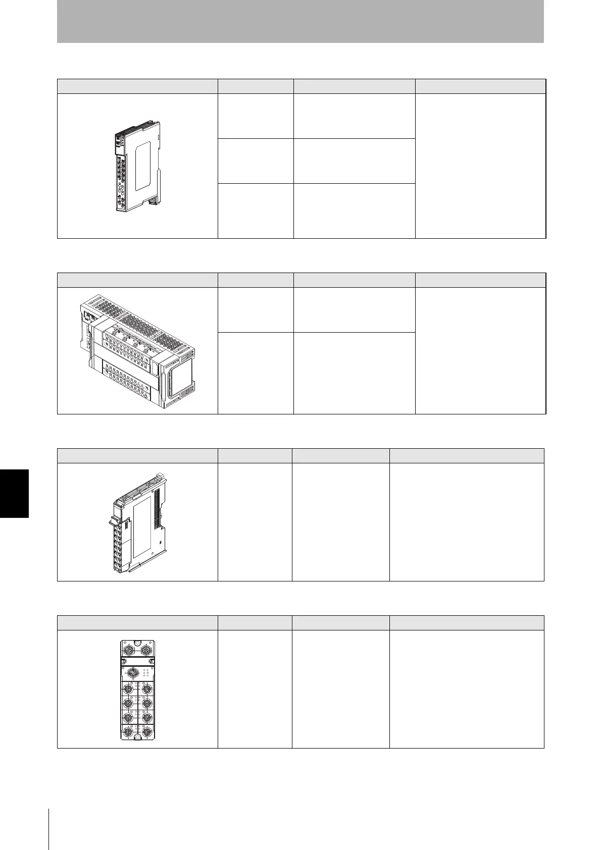
Appearance Model Number of IO-Link ports Remarks
GX-ILM08C 8 • I/O connection terminals: M12
connector (A-cording, female)
• An F39-JGR3K Root-Plug Cable for
Extended and an F39-JGB-L Double-
Ended Cable are required.
• An F39-SGIT-IL3 Intelligent Tap is
required to connect to IO-Link.

 Loading...


