71
F3SG-SR
User’s Manual
Chapter2 Muting
System Operation and Functions
E
To enable the MUTING state, D3 and d2 must satisfy formulas (3) and (4), respectively.
This distance must prevent the MUTING state from being enabled by a person passing through the
muting sensors. Also, install the F3SG-SR and muting sensors so that each workpiece passes through
all muting sensors before the next workpiece arrives at the first muting sensor.
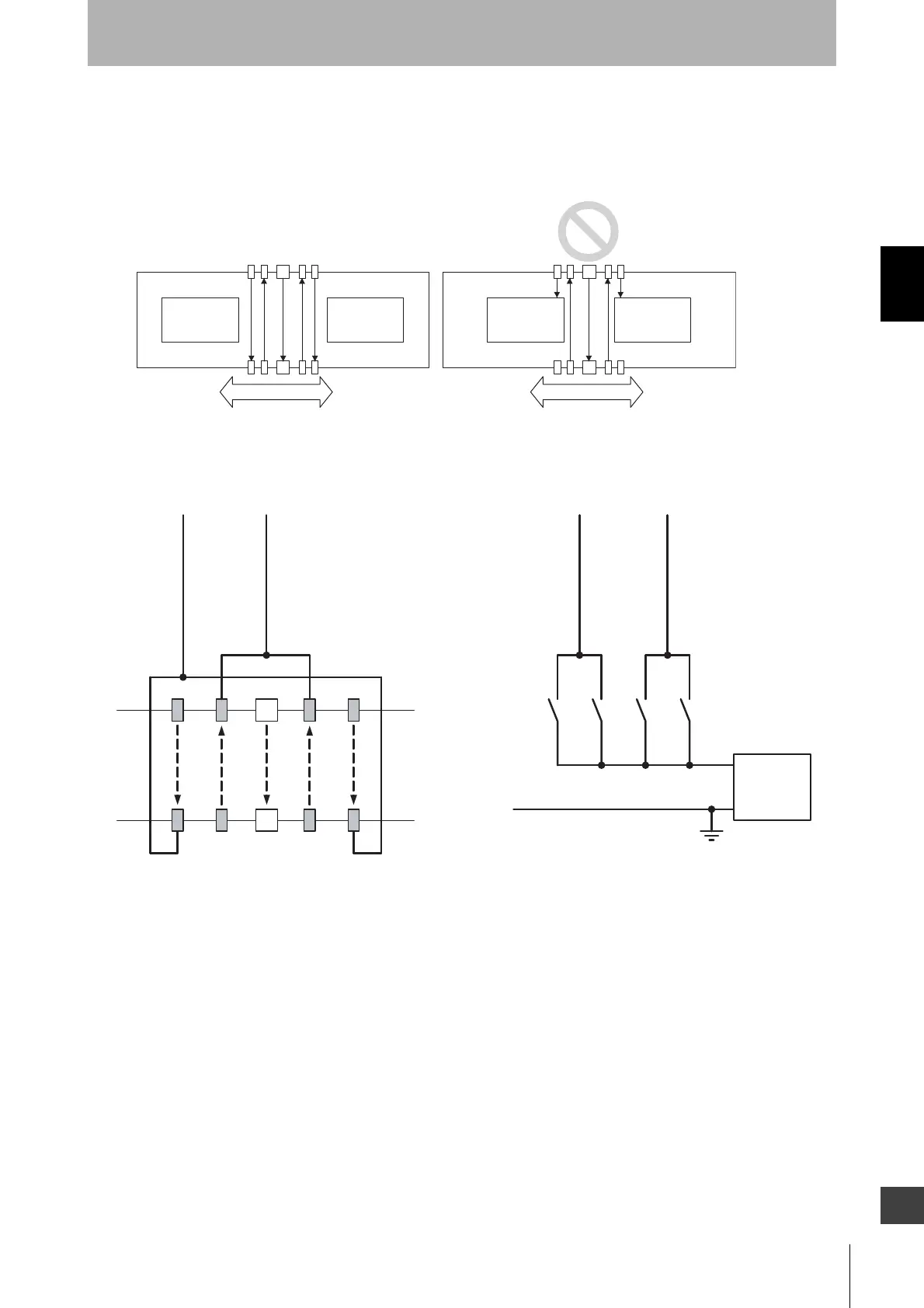
Wiring diagram (PNP)
Moving direction
Workpiece Workpiece Workpiece Workpiece
Moving direction
+24 VDC
0 V
Power
supply
A2A1 B2B1
MUTE A: Gray
B2
A1 A2
B1
F3SG-SR
Using a photoelectric sensor as a muting sensor
Note. Two-wire type muting sensor cannot be used.
Using an NO contact type switch as a muting sensor (PNP)
A1, B1, A2, B2 :
Through-beam type
photoelectric sensor
- PNP Output
- Dark-ON
A1, A2, B1, B2:
NO contact type switch
MUTE B: Pink
MUTE A: Gray
MUTE B: Pink

 Loading...


